


Special offers from our partners!

Find Replacement BBQ Parts for 20,308 Models. Repair your BBQ today.

9
Vermont Castings EWF36A
20005167
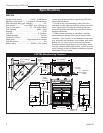
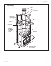
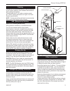
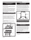
Framing
Framing can be constructed before or after the fireplace
is set in place, however, most installers build the frame
before setting the fireplace.
Frame fireplace with 2 x 4 lumber or heavier materi-
als. Refer to framing dimensions in Figure 1 for basic
fireplace specifications.
NOTE: Framing should be positioned to accommodate
wall covering and fireplace facing material.
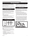
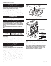
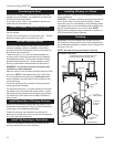
EB1 (Receptacle) Hookup
Option for Circulating Models Only
Wiring should be installed by a certified electrician.
Turn off circuit breaker before wiring models.
Once fireplace is secured, complete wiring the fan kit.
Remove knockout in the center of the back of the EB1
and install listed cable clamps. Feed electrical wire
through listed cable clamp leaving approximately six (6)
inches of wire exposed through the EB1. Secure listed
cable clamp to the wire.
Attach white wire from power source to one (1) wire
of receptacle and secure with nut. Attach black wire
from power source to the other wire of receptacle and
secure with nut. Be sure nuts are secured tightly.
Secure EB1 assembly to inside of electrical box cover-
plate using two screws. Attach cover to face of the EB1
while being careful to position excess wire completely
within the EB1, then attach coverplate to fireplace.
Chimney Set-Up
Since you have already planned the chimney run, you
should know exactly how the installation is to be ac-
complished - how much pipe is required, the number of
elbows, if any, and type of termination to be used.
CAUTION: Report to your dealer any parts damaged
in shipment, specifically check the end connection of
chimney sections and elbows.
NOTE: The EWF36A fireplace must use CFM Corpora-
tion model triple wall 8” chimney components only. The
installation procedure described in this manual applies
only to this system.
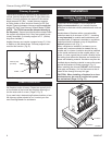
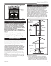
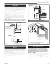
Straight-Up Chimney Installation
To mark the centerline of the flue, put the fireplace
in final position and measure out from the wall: 9¹⁄₂"
(241mm). Mark a spot on the ceiling directly above the
fireplace. Draw a line parallel to the back wall through
this mark. (Fig. 8)
Using a plumb bob positioned directly over center point
of fireplace flue collar, mark the ceiling to establish the
chimney center point. (Fig. 8)
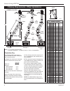
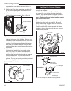
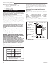
Offset Installation
In order to clear an obstruction, it may be necessary to
offset chimney from vertical. This is accomplished by
using elbows. Use the 30˚ Offset Elbow table on Page 6
to determine proper offset and parts required.
Each offset requires two (2) elbows. The second elbow
is equipped with support straps. It is very important to
install the second elbow in each offset as close to the
ceiling or support as possible so that the elbow straps
can be secured to framing members to help support the
weight of the chimney.
Determine offset distance of your chimney arrangement
from centerline of fireplace to centerline of chimney
where it is to pass through ceiling.
Locate center point of the chimney on ceiling as though
a straight up chimney arrangement is to be used. Mea-
sure your offset dimension from straight up chimney
center point on ceiling.
FPC556a
EPA36
LOCATE CENTER LINE
Circulating model
3/20/02 djt
9"
(241mm)
Chimney Centerline
Actual Centerpoint
Plumb Line
Plumb Bob
Imaginary Cen-
terpoint
FPC556a
Fig. 8 Locate centerline of chimney with plumb line.