


Special offers from our partners!

Find Replacement BBQ Parts for 20,308 Models. Repair your BBQ today.
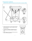
2. The system has a thermal element that
will shut off the flow of gas between 240° F
and 300° F.
3. The system has a flow-limiting device
which when activated, will limit the flow of
gas to 10 cubic feet per hour.
4. The pressure regulator and hose assem-
bly provided is factory set at an outlet pres-
sure of 11 inches water column (.4 lb. per
sq. inch).
WARNING: Any attempt to adjust the
regulator is dangerous and could create
a situation causing personal injury or
property damage. Consult your L.P. gas
dealer if you think the regulator is not
working properly.
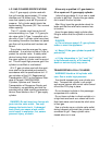
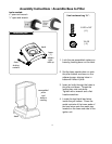
L.P. GAS SUPPLY CYLINDER
NOTE: AN L.P. CYLINDER IS NOT
INCLUDED WITH THIS GRILL MODEL.
An L.P. cylinder can be obtained at the
store where you purchased your grill or
from an authorized L.P. gas dealers.
6
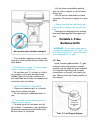
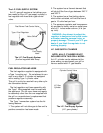
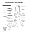
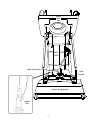
The L.P. FUEL SUPPLY SYSTEM
An L.P. gas grill requires a fuel delivery sys-
tem made up of an L.P gas supply cylinder, a
fuel regulator with hose and a gas-control
valve.
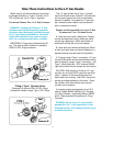
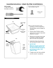
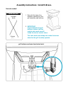
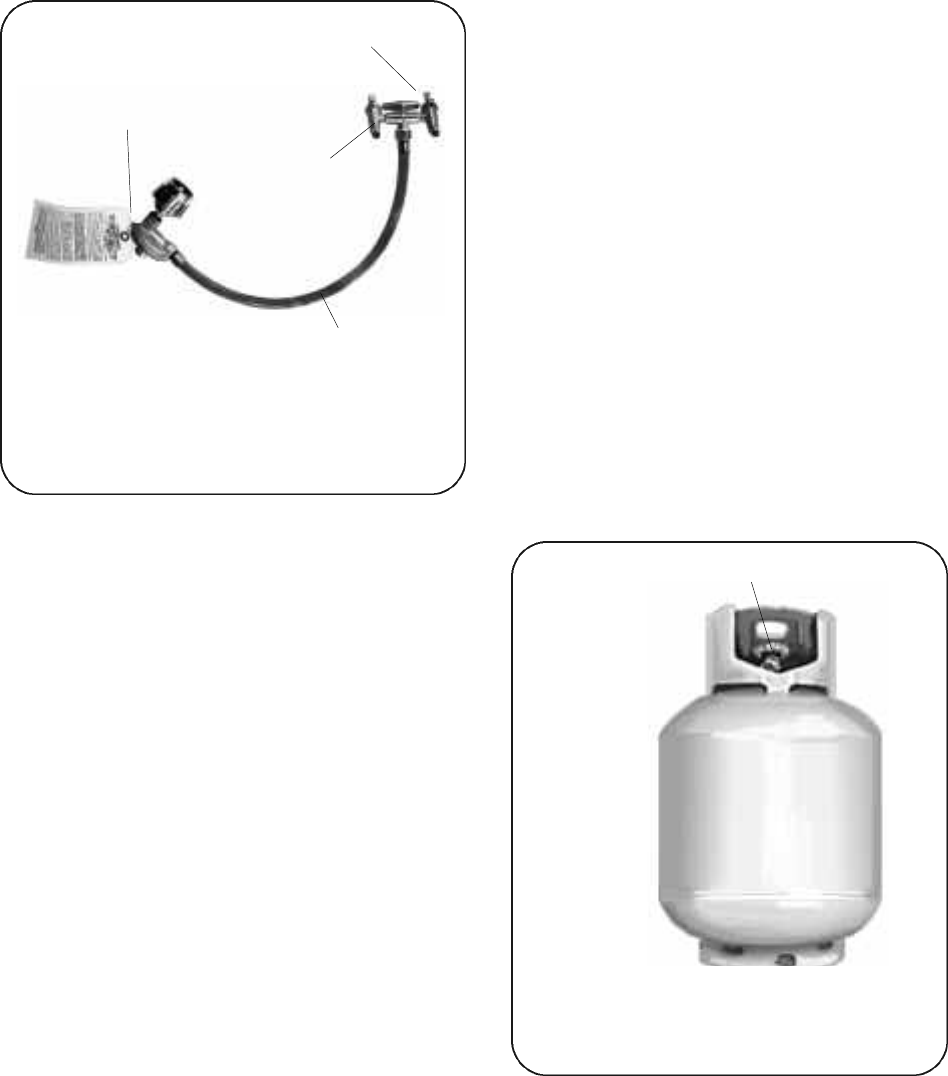
FUEL REGULATOR AND HOSE
The fuel regulator supplied is equipped with
a Type 1 coupling nut. Do not attempt to con-
nect to any other L.P cylinder not equipped
with a mating Type 1 cylinder valve.
This grill is not to be used with any other cylin-
der connection device.
The fuel regulator and hose assembly with
the Type 1 fitting supplied must be used with
the appliance. Do not use a hose and regula-
tor assembly other than the one supplied with
the grill or a manufacturer’s replacement fuel
pressure regulator assembly.
The Type 1 connection system has the fol-
lowing features:
1. The system will not allow gas to flow until a
positive connection has been made.
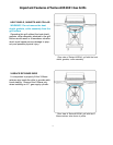
L.P. Gas
Cylinder
Cylinder Control Valve
The L.P. Fuel Supply System
(L.P. gas cylinder)
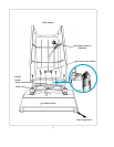
Type 1 Fuel Regulator
Dual Burner Fuel-Control Valve
Fuel Supply
Hose
Valve Orifice
The L.P. Fuel Supply System
(the fuel regulator and hose)