


Special offers from our partners!

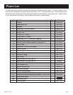
Find Replacement BBQ Parts for 20,308 Models. Repair your BBQ today.

B100539-2-0610 Page 11
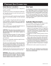
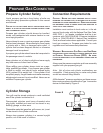
Gas Type
Your Broilmaster
®
side burner is factory equipped for
LP gas and must be converted for use with Natural gas
grills. Never use liquid propane gas with a grill designed
for natural gas, or natural gas with a grill designed for
liquid propane gas. The type gas required for your grill
can be determined from its product identication label.
Questions regarding different types of gases should be
directed to your gas company.
ca u t i O n : ne v e r u S e liq ui d P r O P a n e G a S in a G r i l l
d e S i G n e d f O r n a t u r a l G a S , O r n a t u r a l G a S in a G r i l l
d e S i G n e d f O r li qu id P r O P a n e G a S . qu e S t i O n S r e G a r d -
i n G d i f f e r e n t t y P e S O f G a S e S S h O u l d B e d i r e c t e d t O
y O u r l O c a l G a S c O M P a n y .
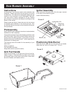
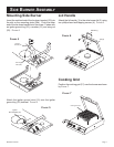
Side Burner Location
Your grill and side burner have been designed for
outdoor use ONLY.
This side burner mounts on the right side of a Broilmas-
ter
®
gas grill and cannot be used with another grill or
for any other purpose.
You should never install or operate your grill and side
burner in any building, garage, or other enclosed
area.
For your safety, the grill and side burner should not be
installed or operated under any combustible materi-
als, such as carports, covered porches, awnings, or
overhangs.
Never install or use your grill and side burner in or on
any recreational vehicle or boat.
a minimum clearance of sixteen (16") inches is required
from all sides of the side burner to any combustible
material. Refer to the grill’s Owner’s Manual for specic
grill clearances.
Examples of combustible materials are patio furniture,
fences, or the wall of your home.
The area surrounding the grill and side burner should be
clear to ensure proper ventilation. Do not obstruct the
ow of combustion and ventilation air in any way. The
ventilation openings on the propane cylinder enclosure
must also remain free and clear of debris.
Portable grills with side burners should be level and
positioned away from direct wind prior to each use.
cautiOn: th e i n S ta l l at i O n a n d O P e r a t i O n O f t h i S
G r i l l a n d S i d e B u r n e r a t c l e a r a n c e S l e S S t h a n S P e c i -
f i e d B e l O w M a y c a u S e a f i r e , P r O P e r t y d a M a G e , O r
P e r S O n a l i n j u r y .
warninG: dO n O t i n S t a l l O r O P e r at e t h i S G r i l l
a n d S i d e B u r n e r w h e r e G a S O l i n e O r O t h e r f l a M M a B l e
M a t e r i a l S a r e u S e d O r S t O r e d . fa i l u r e t O c O M P l y
w i t h t h i S w a r n i n G c O u l d r e S u l t in e x P l O S i O n O r f i r e
c a u S i n G P r O P e r t y d a M a G e O r P e r S O n a l i n j u r y .
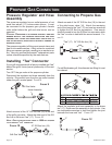
1. Remove burner cap.
2. Remove 2 phillips screws from burner head. Im-
portant: Do not discard this screw; it will be rein-
stalled.
3. Use a 7 mm nut driver or socket wrench to remove
the LP orice and replace it with the Natural gas
orice supplied.
4. Replace the 2 phillips screw into burner head.
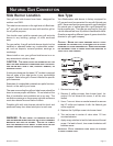
5. Turn set screw in center of valve stem 1/2 turn
counterclockwise.
6. Apply soapy solution to test for leaks around the set
screw. If a leak is found, turn screw clockwise until
bubbles cease.
i
m p o r ta N t : pl a c e c o N v e r s i o N l a b e l i N s i d e l i d a d j a c e N t
t o s e r i a l N u m b e r l a b e l .
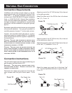
NATURAL GAS CONNECTION