


Special offers from our partners!

Find Replacement BBQ Parts for 20,308 Models. Repair your BBQ today.
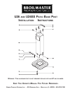
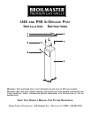
The U48 and P48 In-Ground Posts are only for
use with Broilmaster
®
Gas Grills. Before
proceeding with installation read your Owner’s
Manual for the proper location and minimum
clearances to combustible materials for your grill
and in-ground post.
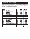
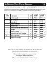
Verify that all parts listed in the exploded view of
this product have been included before beginning
this installation.
Recommended Tools:
• Two adjustable wrenches or a socket set
• A medium Phillips screwdriver
• Pipe thread sealer or Teflon tape (for gas
connections)
• Soapy water solution (to test for leaks)
IN-GROUND POST INSTALLATION 16
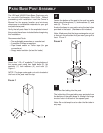
Dig a hole approximately 12" in diameter and 24"
in depth at the desired grill location.
Note: “Normal Installation” height is achieved
when the top of the in-ground post (7) is 25 1/4"
above ground. This height provides a cooking
surface height of 34 1/2" above ground when
grids are placed in the high level position.
Carefully lower the in-ground post into the hole
using the following guidelines:
• The rectangular cut-out is located near the
TOP of the post and should be above ground
after installation.
• The rectangular cut-out must face in the
SAME direction as the front of the grill.
• Hole depth and post measurements should be
checked to ensure desired height.
Note: Make any adjustments at this time.
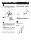
Prepare concrete or a standard pre-mix
according to the manufacturer’s package
directions.
Position the post in the center of the hole. A level
should be used when aligning the post to achieve
precise vertical alignment. Hold the post in place
while pouring the concrete mixture into the hole
around the post.
2
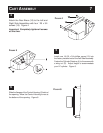
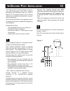
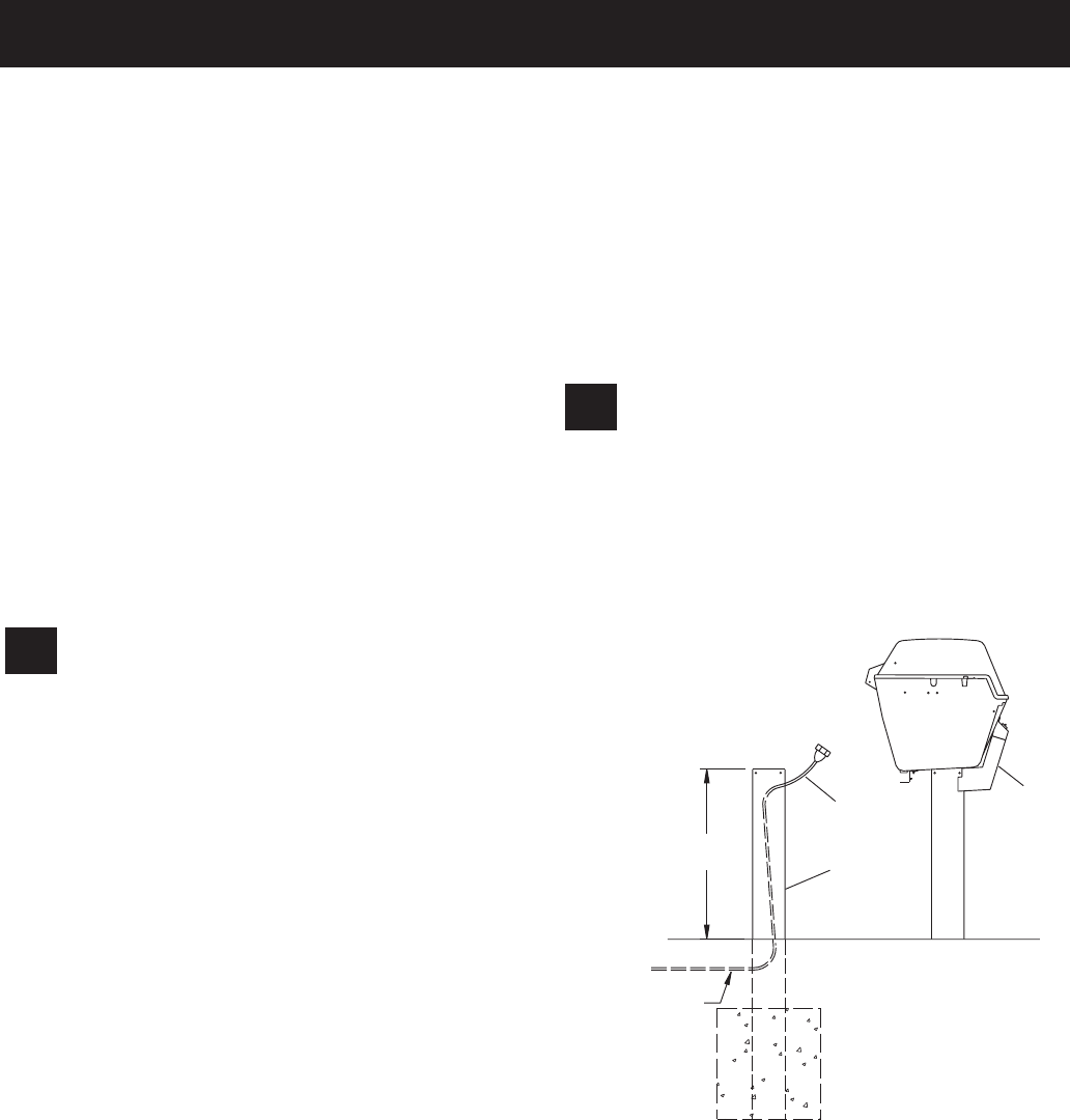
After the concrete has set, insert the tubing (6) in
the post. Figure 1.
Note: Do not attempt to cut or alter the flex tube in
any way.
1
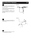
CAUTION: THE CONCRETE MIXTURE MUST NOT
COVER THE GAS SUPPLY ENTRY HOLE ON THE POST.
T
HE GAS SUPPLY ENTRY HOLE (2" DIAMETER HOLE)
IS LOCATED 18 3/4" FROM THE BOTTOM OF THE
POST
.
Make a final alignment check with the level, and
adjust as needed. Allow concrete to set (usually
24 hours).
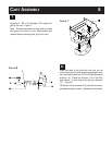
6
7
25-1/4"
GAS
SUPPLY
PIPING
SYSTEM
8
FIGURE 1