


Special offers from our partners!

Find Replacement BBQ Parts for 20,308 Models. Repair your BBQ today.
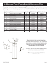
Page 7
B101074-0-1006
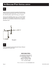
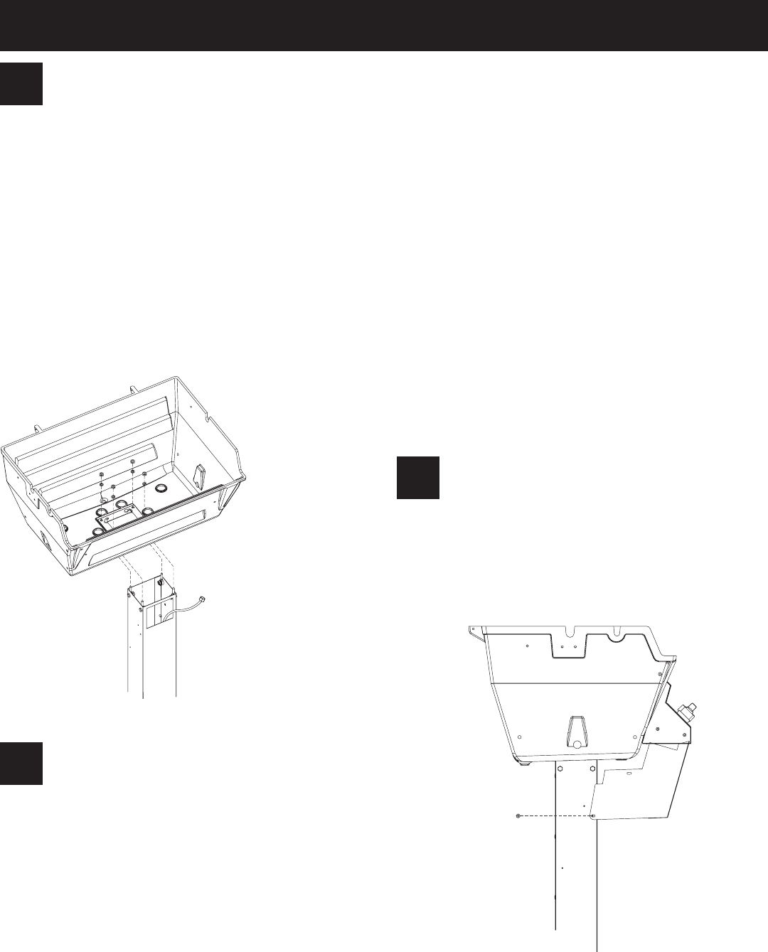
Insert a 1/4 - 20 x 3/4" bolt (5) through one of the four
holes in the top of the post. Fasten a 1/4 - 20 1 3/4
eyebolt (4), 9/32 ID x 5/8 OD flat washer (1), 1/4 lock
washer (2), and 1/4 - 20 hex nut (3) to the 1/4 - 20 x
3/4 bolt (5) inside the post. Repeat this process for the
three remaining holes. Figure 3.
Place the grill bottom on top of the post with the four
eyebolts protruding through the holes located on the
grill bottom.
Secure the grill bottom to the post by placing a 1/4
lock washer and 1/4 - 20 hex nut onto each of the four
eyebolts. Figure 3.
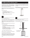
Arrange with your local gas company or licensed con-
tractor to have a gas supply line connected to the inlet
of the stainless steel flex tube assembly. The gas supply
must have a shutoff valve inside the wall and must be
shutoff when the grill is not in use.
Use pipe thread sealant or Teflon tape at the threads
of each connection being careful to not allow any of
these materials into the flare seat. Test for gas leaks
as directed by the grill’s Owners Manual.
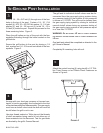
Attach the control housing (6) using two #8 x 1/2" Phil
-
lips Truss Screws or two Plastic Panel Fasteners as
shown in Figure 4.
IN-GROUND POST INSTALLATION
3
FIGURE 3
4
5
FIGURE 4
The grill and its individual shutoff valves must be dis-
connected from the gas supply piping system during
any pressure testing of that system at test pressures
in excess of 1/2 PSIG. The grill must be isolated from
the gas supply piping system by closing its individual
manual shutoff valves during any pressure testing of
the gas supply piping system at test pressures equal
to or less than 1/2 PSIG.
WARNING: D
O NOT SUPPLY LP GAS TO A GRILL DESIGNED
FOR NATURAL GAS OR NATURAL GAS TO A GRILL DESIGNED FOR
LP GAS.
Gas leak tests should be completed as directed in the
grill Owner’s Manual.
Completely fill remaining hole with soil.