


Special offers from our partners!

Find Replacement BBQ Parts for 20,308 Models. Repair your BBQ today.

Page 6
B101074-0-1006
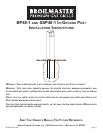
The BP48 and SSP48 In-Ground Posts are only for use
with Broilmaster Gas Grills. Before proceeding with
installation read your Owner’s Manual for the proper
location and minimum clearances to combustible ma-
terials for your grill and in-ground post.
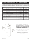
Verify that all parts listed in the exploded view of this
product have been included before beginning this in
-
stallation.
Recommended Tools:
• Two adjustable wrenches or a socket set
• A medium Phillips screwdriver
• Pipe thread sealer or Teflon tape (for gas connec
-
tions)
• Soapy water solution (to test for leaks)
Dig a hole approximately 12" in diameter and 24" in
depth at the desired grill location.
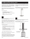
Note: “Normal Installation” height is achieved when the
top of the 48" post (7) is 25 1/4" above ground. This
height provides a cooking surface height of 34 1/2"
above ground when grids are placed in the high level
position.
Carefully lower the in-ground post into the hole using
the following guidelines:
• The rectangular cut-out is located near the TOP of
the post and should be above ground after installa
-
tion. Figure 1.
• The rectangular cut-out must face in the SAME
direction as the front of the grill.
• Hole depth and post measurements should be
checked to ensure desired height.
Note: Make any adjustments at this time.
Prepare concrete or a standard pre-mix according to
the manufacturer’s package directions.
Position the 48" post in the center of the hole. A level
should be used when aligning the post to achieve precise
vertical alignment. Hold the post in place while pouring
the concrete mixture into the hole around the post.
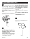
After the concrete has set, insert the stainless steel flex
tube assembly in the post. Figure 2.
Note: Do not attempt to cut or alter the stainless steel
flex tube assembly in any way.
C
AUTION: THE CONCRETE MIXTURE MUST NOT COVER THE GAS
SUPPLY ENTRY HOLE ON THE POST. THE GAS SUPPLY ENTRY HOLE
(2" DIAMETER HOLE) IS LOCATED 18 3/4" FROM THE BOTTOM
OF THE POST.
Make a final alignment check with the level, and adjust
as needed. Allow concrete to set (usually 24 hours).
FIGURE 2
1
IN-GROUND POST INSTALLATION
2
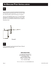
25-1/4"
GAS SUPPLY
PIPING SYSTEM
FIGURE 1