


Special offers from our partners!

Find Replacement BBQ Parts for 20,308 Models. Repair your BBQ today.
B101586-7-1012Page 20
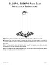
in-ground poSt ASSEmbly
NOTICE: Assemble and install patio base before assem-
bling grill.
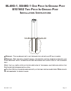
The SS48G and BL48G In-Ground Posts are only for use with
Broilmaster Gas Grills. Before proceeding with installation read
your Owner’s Manual for the proper location and minimum clear-
ances to combustible materials for your grill and in-ground post.
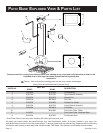
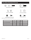
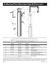
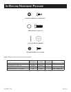
Verify that all parts listed in the exploded view of this product have
been included before beginning this installation.
Recommended Tools:
• Drill/Driver
• Two adjustable wrenches or a socket set
• A medium Phillips screwdriver
• Pipe thread sealer or Teon tape (for gas connections)
• Soapy water solution (to test for leaks)
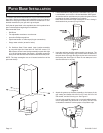
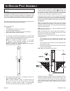
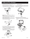
1. For two piece in-ground post using eight 10 x 1/2 Hex Head
screws. Use black screws for black posts. For this application, use
top set of holes in post assembly. See Figure 1.
NOTE: For SS48G and BL48G models, it is an option
to purchase a Post Extension through your Broilmas-
ter Dealer to increase Post Assembly length .
NOTE: The extension is available on the 48” post for applica-
tions that may need more height.
Figure 1
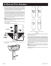
2. Dig a posthole approximately 12” in diameter and 28 3/4” in
depth at the desired grill location.
Note: “Normal Installation” height is achieved when the
top of the 48” post is 24 3/4” above ground. This height
provides a cooking surface height of approximately
34” above ground when grids are placed in the high level.
The gas supply line should be installed according to local
codes to prevent damage from digging.
CAUTION: The
gas supply line must be regulated (In the case of Natural gas
that means connected after your gas meter and regulator)
and that you have an easily accessible shut-off valve.
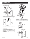
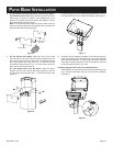
At the access door connect a 3/8” are coupling (not supplied
by Empire) to the gas supply line and stainless steel tubing.
Position the tubing in the top notch of the post. Bend the ex
tube at the top end to match the Feed Line of the grill valve.
See Figure 2.
Note: Use pipe thread sealant or Teon tape at the threads
of each connection being careful to not allow any of these
materials into the are seat. Test for gas leaks as directed by
the grill’s Owners Manual
Note: Do not attempt to cut or alter the stainless steel ex
tube assembly in any way.
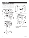
Note: For R Series Grills, a Cover Plate will be supplied, so
the Flex Line will have to go through the hole on the cover
plate before mounting the Grill bottom.
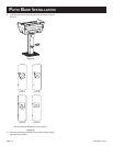
Carefully lower the in-ground post into the hole using the fol-
lowing guidelines:
• The rectangular cut-out is located near the TOP of the
post and should be above ground after installation. See
Figure 1.
• The rectangular cut-out must face in the SAME direction
as the front of the grill.
• Hole depth and post measurements should be checked
to ensure desired height.
Note: Make any adjustments at this time.
Figure 2
Prepare concrete or a standard pre-mix according to the man-
ufacturer’s package directions. Position the 48” post in the
center of the hole. A level should be used when aligning the
post to achieve precise vertical alignment. Hold the post in
place while pouring the concrete mixture into the hole around
the post.