


Special offers from our partners!

Find Replacement BBQ Parts for 20,308 Models. Repair your BBQ today.
Heat & Glo LifeStyle Collection • Dakota 42-B/Dakota 42H-B • 4036-909 Rev D • 08/06 13
Battery polarity must be correct or module damage will
occur.
CAUTION
Note: This appliance must be electrically wired and grounded
in accordance with local codes or, in the absence of local
codes, with National Electric Code ANSI/NFPA 70-latest
edition or the Canadian Electric Code, CSA C22.1.
A. Recommendation for Wire
Shock Risk
Explosion Risk
Do NOT wire 110V to valve.
Do NOT wire 110V to wall switch
• Incorrect wiring will damage millivolt
values.
• Incorrect wiring will override IPI safety
lockout and may cause explosion.
WARNING
• Keep wire lengths short as possible by removing any
excess wire length, not to exceed 18 ft.
• Low voltage and 110 VAC voltage cannot be shared within
the same wall box.
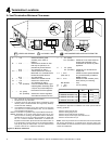
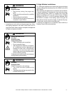
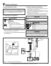
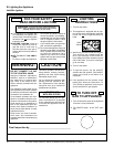
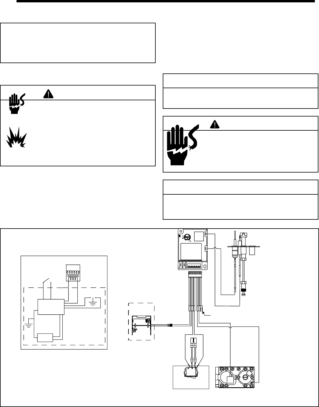
C. Intellifi re Ignition System Wiring
• This appliance is equipped with an Intellifi re control valve
which operates on a 3 volt system.
• This appliance is supplied with a battery pack which is
located in the ON/OFF switch terminal box. A wiring
diagram is shown in Figure 7.1.
• The battery pack requires two D cell batteries (not
included). See Section 12.B. for battery replacement.
7
7
Electrical Information
Label all wires prior to disconnection when servicing
controls. Wiring errors can cause improper and dangerous
operation. Verify proper operation after servicing.
CAUTION
Shock Risk
• Replace damaged wire with type 105° C
rated wire.
• Wire must have high temperature
insulation.
WARNING
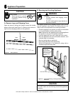
B. Connecting to the Appliance
IGNITION MODULE
3 VAC
GRN
ORG
INTERMITTENT
PILOT
IGNITOR
IGNITION
MODULE
(3V)
ON/OFF
WALL
SWITCH
LOW VOLTAGE
BATTERY
PACK
FLAME SPARKER/
SENSOR
SEE NOTE 1
ORG
WHT
PIGGYBACK
ON/OFF SWITCH
BRN
BRN
VALVE
VALVE
GROUND TO
FIREPLACE
CHASSIS
I
S
BLACK
RED
BATTERY
PACK
Figure 7.1 Intellefi re Pilot Ignition (IPI) Wiring Diagram