


Special offers from our partners!

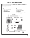
Find Replacement BBQ Parts for 20,308 Models. Repair your BBQ today.
Bezel
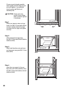
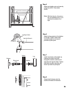
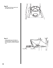
Step 16
Loosen the two M4 bolts with
washers from the bottom of the
burner assembly bracket. This will
allow the burner to move freely
while performing Step 17.
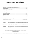
Step 17
Remove two M4 bolts and
washers from the side burner
valve. Insert the side burner
valve assembly through the hole
in the side burner front panel,
seat the valve nozzle into the
burner venturi. Hold in place
while you perform Step 18.
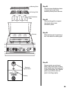
WARNING: Never use your grill
without leak testing all
gas connections and
hoses. See the section
on "Leak Testing" in
this manual for proper
procedures.
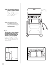
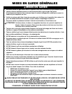
Step 18
Place the bezel over the control
knob mounting stem and position
over holes in side burner base
and side burner valve assembly.
Attach with two M4 X 10mm bolts
with washers which come with
valve. Install the side burner
control knob onto valve stem,
then tighten up the burner
assembly/bracket screws
loosened in Step 16.
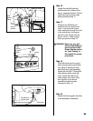
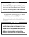
Step 19
Attach side burner igniter lead wire
to the electrode as illustrated.
28
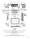
Side
Burner
Control
Knob
Side Burner
Igniter Lead
Electrode
Side
Burner
Valve
Burner Venturi
Valve
Nozzle