


Special offers from our partners!

Find Replacement BBQ Parts for 20,308 Models. Repair your BBQ today.

724-746-5500 | blackbox.com
724-746-5500 | blackbox.com
Page 3
Cold Front Planning Guide
5. The transition frame weighs no more than 40 lb. (18 kg).
2.1.3 Connections and Piping
1. Supply and return connections on the HTD are brass ¾" or 1" ID quick-release couplings conforming to ISO 7241-1 Series B.
The female socket is used for supply water connection, and the male nipple is used for return water connection.
2. Bottom or top entry for the supply/return connection is available.
3. Supply/return headers on bottom-fed models have Schrader
®
valves for manual air bleeding.
4. Drain valve is on bottom of the HTD to allow the coil to drain completely.
5. Piping is copper, bent to minimize joints; any joints should be brazed.
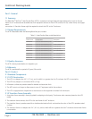
2.1.4 Heat Exchanger Coil
1. Coil is constructed of copper tube and aluminum fin, 2 rows deep, 12 FPI.
2. Heat transferred by coil divided by initial temperature difference is no less than 440 W/°C at 2548 m
3
⁄H (1500 CFM) and
30 L/min (8 GPM) water flow.
3. Coil will be designed to minimize air-side and water-side pressure drops.
4. Maximum air-side pressure drop will not exceed 27 Pa (0.11 in H
2
0) at 4077 m
3
⁄H (2400 CFM) including coil and perforated
sheets.
5. Maximum liquid-side pressure drop will be 53 kPa (7.7 psi) at 38 L/min (10 GPM) including coil, piping, and quick connects.
6. Coil is protected by perforated sheets, no less than 79% open, on both air inlet and air outlet sides.
7. Coil is UL
®
Registered (UL207).
2.1.5 Environmental
1. The HTD doesn’t require electrical power connections.
2. The HTD is a completely passive device and has no fans or other active air movement components.
2.2 Optional Components
2.2.1 Flexible Hose Kits
1. Optional Hose Kits are available to provide for connection between the water distribution manifold and the supported HTD
units and consist of a matched pair of hoses with connections.
2. Hoses will be factory assembled; factory pressure tested, constructed of double-walled reinforced Ethylene Propylene Diene
Monomer (EPDM) rubber and have brass ¾" or 1" ISO 7241-1 Series B quick-release couplings on one or both ends to facilitate
rapid installation and reconfiguration. Hoses with a single quick-release coupling will have ¾" MPT connection on opposite end.
3. Hose material is ¾" or 1" ID with minimum wall thickness of 0.14" (0.36 cm), minimum bend radius of 4" (10.2 cm), and
minimum burst pressure of 12.4 MPa (1800 psi).
4. Hose material meets flammability rating of UL
®
1581 VW-1 or greater.
5. Hose Kits are pressure tested as an assembly to 1.7 MPa (250 psi).
6. Hose Kits are available with either straight connections or right-angle connections. External right-angle Hose Kits require a
minimum clearance of 2.125" (5.4 cm) between the bottom of the HTD/Enclosure and the floor.
7. One (1) hose kit (with a supply and a return hose) shall be supplied per HTD.
2.2.2 Pre-Mixed Treated Water
1. A secondary loop is filled with particulate-free, DI/RO water with appropriate controls to prevent corrosion, fouling,
scaling, and bacterial growth.
2. Water is treated with azole, molybdate, and isothiazoline.