Special offers from our partners!

Find Replacement BBQ Parts for 20,308 Models. Repair your BBQ today.
14
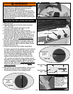
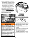
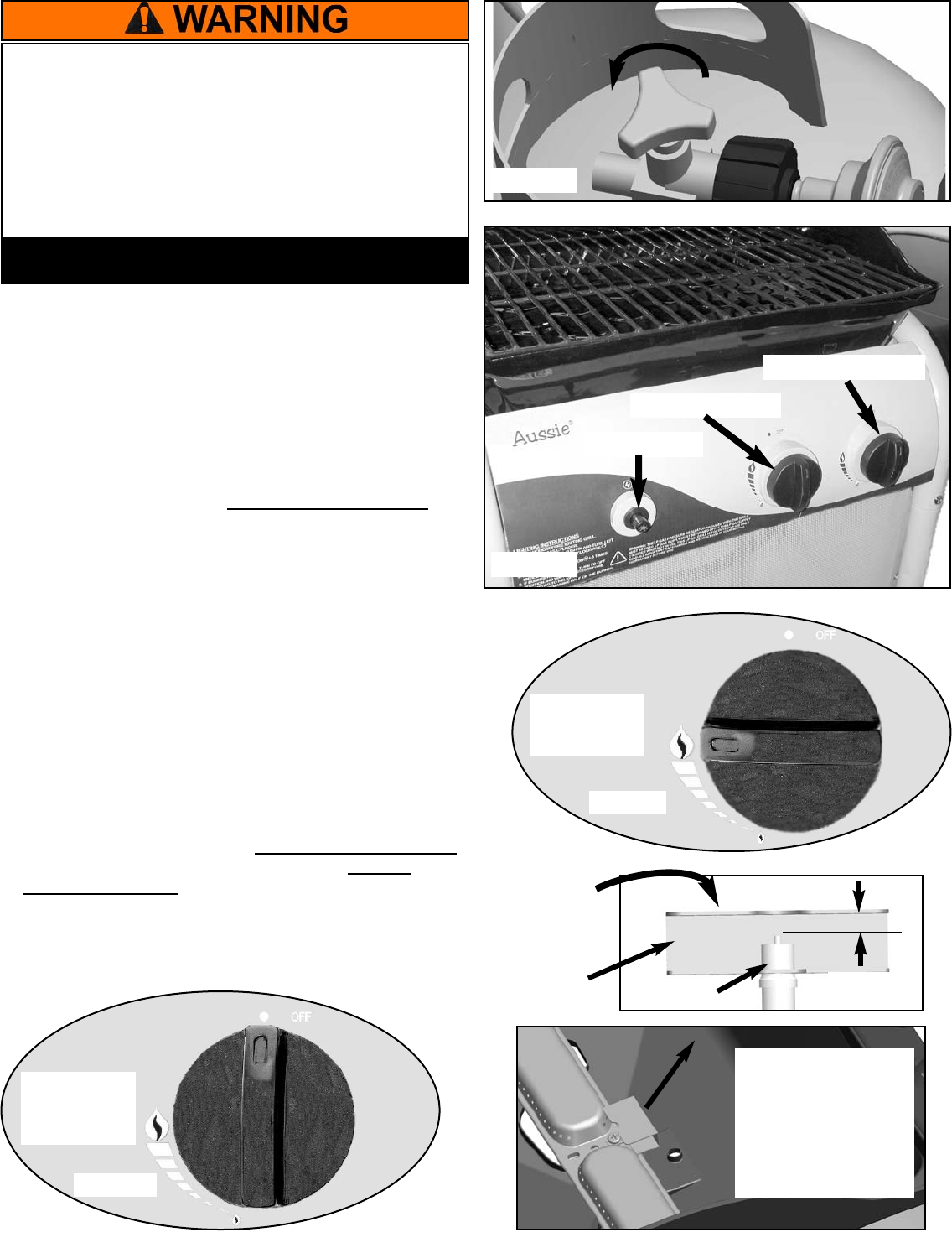
1. Open the Hood.
2. Important: Make sure all control knobs are turned
“Off”. (FIG. 13A)
3. Turn the LP Gas Cylinder valve open counter
clockwise until it stops. (FIG. 13B)
4. Push the left control knob in and turn counter
clockwise to the High flame position. (FIG. 13C & 13D)
5. Pause 4 seconds and push the ignitor button in
several times to light the burner. Listen for the spark
ignition and look to make sure the burner is lit. If no
spark, see (FIG. 13E) and Troubleshooting Section.
6. From the “Off” position, push right control knob in
and turn counterclockwise to the High position. Your
grill has a crossover ignition system that allows the
burner to light each side successively. Make sure the
right side of burner is lit.
7. If either side of burner fails to light, repeat Step 4.
If a burner goes out during operation, turn all knobs to
the “Off” position and close the LP cylinder valve to
dissipate any accumulated gas. Open hood and wait
five minutes before attempting to relight the grill.
If any or all burners fail to light after three or four
attempts following Steps 4-6, turn all knobs to the
“Off” position and close the LP gas cylinder valve to
dissipate any accumulated gas. Wait five minutes; then
repeat the lighting procedures. NOTE: If the burner
still fails to light, refer to the Troubleshooting Section.
The burner can also be lit manually, see Manual
Lighting of the Grill.
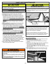
8. After ignition, turn the control knobs to “High” for 3-5
minutes and close the Hood to preheat the grill.
Preheat the grill before every cooking session.
LIGHTING THE GRILL USING THE IGNITOR
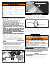
To reduce the risk of serious bodily injury or death:
· Open Hood before lighting the grill to prevent an
explosion from any gas accumulation.
· If lighting attempts fail, or the burners go out during
operation, turn all control knobs “Off” to dissipate any
accumulation of gas. Accidental ignition could occur.
Wait five minutes before repeating lighting procedure.
· Light both left and right sides of burner to prevent gas
from accumulating.
FIG.13A
Control Knob
in OFF
position
FIG.13D
FIG. 13C
FIG. 13B
Left Control Knob
Right Control Knob
Ignitor Button
Control Knob
in HIGH
position
Gas Collector
Box
Electrode
3/16” GAP
If no spark, pinch
together or open Gas
Collector Tab to
adjust 3/16” gap
between electrode tip
and edge of Gas
Collector Tab.
Gas Collector
Tab


