


Special offers from our partners!

Find Replacement BBQ Parts for 20,308 Models. Repair your BBQ today.

14
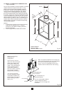
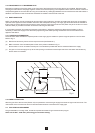
6.4 PILOT ASSEMBLY
The pilot is an atmosphere sensing device and must be replaced as a complete unit. Repair must not be undertaken.
NOTE: If the fire keeps going out or exhibits signs of nuisance shut off, check the operation of the pilot as follows:-
(a) Inspect the pilot flame, if suspect check the gas supply. Clear blockage if necessary. If flame is still suspect replace pilot
assembly.
(b) Check the thermocouple. If faulty replace the pilot assembly.
(c) Check the magnet unit in the gas valve. If faulty replace the valve.
(d) Check the thermocouple break micro switch and connections.
(d) Check the ventilation in the room. Vitiation may be due to lack of sufficient air supply.
(e) Check for satisfactory clearance of combustion products. Vitiation may be due to spillage of combustion products into the
room.
1. Remove burner tray (Section 6.1 above).
2. Release the pilot supply pipe at the pilot end and ease out the pipe.
3. Undo the thermocouple nut at the gas valve end and ease out the thermocouple.
4. Disconnect the thermocouple wires from the yellow micro switch wires.
4. Pull off the spark lead at the pilot end.
5. Remove the two screws securing the pilot assembly (and insulation pad) to its bracket.
6. Fit the new pilot assembly.
7. Re-assemble in the reverse manner.
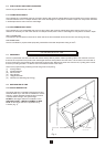
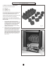
6.5 FUEL EFFECT COMPONENTS
The loose coals and the coal bed simply lift out. To replace the rear coal and/or side cheeks proceed as follows:
SIDE CHEEKS
1. Remove the outer case.
2. Remove the left or right retaining panel by undoing the two screws securing it to the fire body.
3. Slide out the side cheeks and replace with new ones. Re-assemble in reverse order.
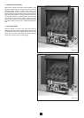
REAR COAL
1. Remove burner tray (Section 6.1)
2. Remove the screws securing the lower coal support and slide out the rear coal.
3. Replace with a new one, and re-assemble in reverse order.
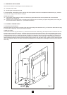
6.6 MAIN BURNER
1. Remove burner tray (Section 6.1)
2. Undo the two screws securing the pilot assembly to the burner.
3. Undo the two screws securing the injector to the burner manifold.
4. Turn the tray upside down.
5. Undo the two screws securing the burner to the tray and remove the burner.
6. Fit the new burner and re-assemble in the reverse manner.
6.7 CONTROL KNOB
1. Remove the outer case.
2. Remove the two screws securing the knob to the slider linkage.
3. Replace with a new knob and re-assemble in the reverse manner.
6.8 IGNITION UNIT
1. Remove the outer case.
2. Disconnect the red and blue wires and the ignition lead from the ignition unit.
3. Undo the two screws securing the ignition unit to its mounting bracket.
4. Replace with a new one and re-assemble in the reverse manner.
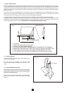
6.9 IGNITION BATTERY REPLACEMENT
1. Remove the outer case.
2. The battery can now be located at the bottom of the fire, fitted into the ignition unit.
3. Remove the old battery from the ignition unit by pulling it out towards the right.
4. Replace with the new battery of the same type (see Section 1.0 Technical Data).
Note: The terminals of the battery are of different shapes to prevent incorrect connection. If it does not fit, try it the other way
round.
5. Re-fit the outer case.