


Special offers from our partners!

Find Replacement BBQ Parts for 20,308 Models. Repair your BBQ today.

6
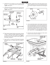
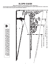
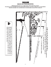
12. Assemble a wheel with the valve stem facing out onto
the axle. Assemble a hub cap (Q) by pressing or tapping
it onto the axle. Repeat on other end of axle. See fi gure
6.
FIGURE 5
FIGURE 4
10. Place the front tongue inside the rear tongue as shown
in fi gure 5. Fasten the tongues together using a 3/8"
x 4" hex bolt (A) and a 3/8" nylock nut (M).
Tighten,
leaving the nut just loose enough that the tongues can
pivot freely. See fi gure 5.
11. Insert the 3/8" x 4" clevis pin (G) through the tongues
and secure with a 1/8" hairpin cotter (N), as shown in
fi gure 5.
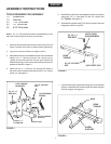
8. Assemble the hitch bracket to the front tongue using
two 3/8" x 1" hex bolts (B)
and 3/8" nylock nuts (M).
Tighten.
See fi gure 4.
9. Assemble the leg stand bracket to the front tongue using
two 5/16" x 1" hex bolts (C) and 5/16" nylock nuts (L).
Tighten.
See fi gure 4.
FIGURE 7
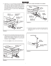
13. Turn the assembled tongue, wheel support and wheels
over to the upright position. Place the latch stand bracket
onto the tongue between the latch lock assembly and
the raised tab. Place the poly tray onto the wheel support
and latch stand bracket. Fasten the tray to the wheel
support using eight 5/16" x 3/4" truss head bolts (F) and
5/16" nylock nuts (L).
Do not tighten yet.
See fi gure
7.
14. Place the latch stand plate between the latch stand
bracket and the poly tray. See fi gure 7.
FIGURE 6
(L) 5/16"
NYLOCK NUT
(F) 5/16" x 3/4"
TRUSS HEAD
BOLT
LATCH STAND
BRACKET
LATCH
STAND
PLATE
(Q) HUB CAP
WHEEL
AXLE
FRONT
TONGUE
(B) 3/8" x 1"
HEX BOLT
(M) 3/8" NYLOCK
NUT
HITCH
BRACKET
LEG STAND
BRACKET
(C) 5/16" x 1"
HEX BOLT
(L) 5/16" NYLOCK
NUT
FRONT
TONGUE
(M) 3/8"
NYLOCK NUT
(A) 3/8" x 4"
HEX BOLT
(G) 3/8" x 4"
CLEVIS PIN
(N) 1/8" HAIRPIN
COTTER
ENGLISH