


Special offers from our partners!

Find Replacement BBQ Parts for 20,308 Models. Repair your BBQ today.
GAS
Fixed piping installations
• Check with local gas utility
company or with local codes
for instructions on installing
gas supply lines. All gas
connections should be made
by a competent technician and
in accordance with local codes
and or ordinances. In the
absence of codes, the
installation must comply with
the National Fuel Gas Code
ANSI Z223.1.
• An installer-supplied gas shut-
off valve must be installed in
an easily accessible location.
All installer-supplied parts
must conform to local codes.
• Must be isolated from the gas
supply piping system by closing
its individual manual shut-off
valve during any pressure
testing of that system at test
pressures equal to or less than
1/2 psi (3.5 kPa).
Natural gas models
• Water column pressure
o Operating pressure—4.0"
WCP
o Supply pressure of 6" – 10"
WCP
o If incoming pressure exceeds
10" WCP, a step-down
regulator is required.
• Accepts standard residential
1/2” (1.3 cm) ID gas service
line; 1/2” (1.3 cm) NPT male
with 7/8” (2.2 cm) flare adapter.
o If using a Viking GSH12
flexible hose, remove the
1/2” (1.3 cm) flare adapter
and attach hose to the 7/8”
(2.2 cm) male flare on the
regulator assembly.
LP/propane models
• Water column pressure
o Operating pressure—
10” WCP
o Supply pressure of 11” – 14”
WCP (for fixed piping
installations)
o If incoming pressure exceeds
14” WCP, a step-down
regulator is required.
• Accepts standard residential
1/2” (1.3 cm) ID gas service
line; 1/2” (1.3 cm) NPT male
with 3/8” (0.95) flare adapter.
LP/propane tank installations
• Water column pressure
o Operating pressure—
10” WCP
• Includes high-capacity
hose/regulator assembly for
connection to a standard 5-
gal./20-lb. (approx. 12”
diameter/18”H.) LP/propane
gas cylinder equipped with a
Type 1, QCC-1 connector
o The cylinder connection
device must be compatible
with the Type 1, QCC-1
connector on the outdoor
cooking appliance.
o The cylinder must be
provided with a shut-off valve
terminating in an LP/propane
gas supply cylinder valve
outlet specified.
o The cylinder supply system
must be arranged for vapor
withdrawal and provided
with a listed OPD (overfilling
prevention device).
ELECTRICAL
• T-Series models
o 9-volt DC battery for
electronic ignition
o Rotisserie motor max. amp
usage—6.0
• E-Series models
o 3’ (91.4 cm) power cord
supply cord with 3-prong
grounded plug attached to
grill
• 120 VAC/60 Hz
o Grill max. amp usage
• VGBQ300—2.1
o 2’ (61.0 cm) power cord supply
cord with 3-prong grounded
plug attached to rotisserie
motor.
• 120 VAC/60 Hz
o Rotisserie motor max. amp
usage—6.0
PLUMBING
Not applicable
PLANNING AND DESIGN GUIDE
VIKINGRANGE.COM • 1-888-VIKING1
RELEASED 12/1/07
©2007 VRC—INFORMATION SUBJECT TO CHANGE
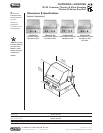
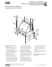
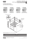
OUTDOOR—COOKING
30”W. Premium T-Series & Ultra-Premium
T-Series/E-Series Gas Grill
UTILITY
REQUIREMENTS
Installation Requirements
VGBQ030-2T VGBQ300-2RT/E VGIQ300-2RT
Surface burner rating
Standard SS grill burners (each)
25,000 BTU (7.3 kW) Nat./22,500 BTU (6.5 kW) LP
Smoker burner (split standard)
12,500 BTU (3.7 kW) Nat./ 12,500 BTU (3.7 kW) Nat./
10,500 BTU (3.1 kW) LP 10,500 BTU (3.1 kW) LP
Gourmet-Glo™ rotisserie burner
15,000 BTU (4.4 kW) Nat./ 15,000 BTU (4.4 kW) Nat./
13,500 BTU (4.0 kW) LP 13,500 BTU (4.0 kW) LP
TruSear infrared burner 3
0,000 BTU (8.8 kW) Nat./LP
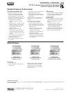
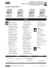
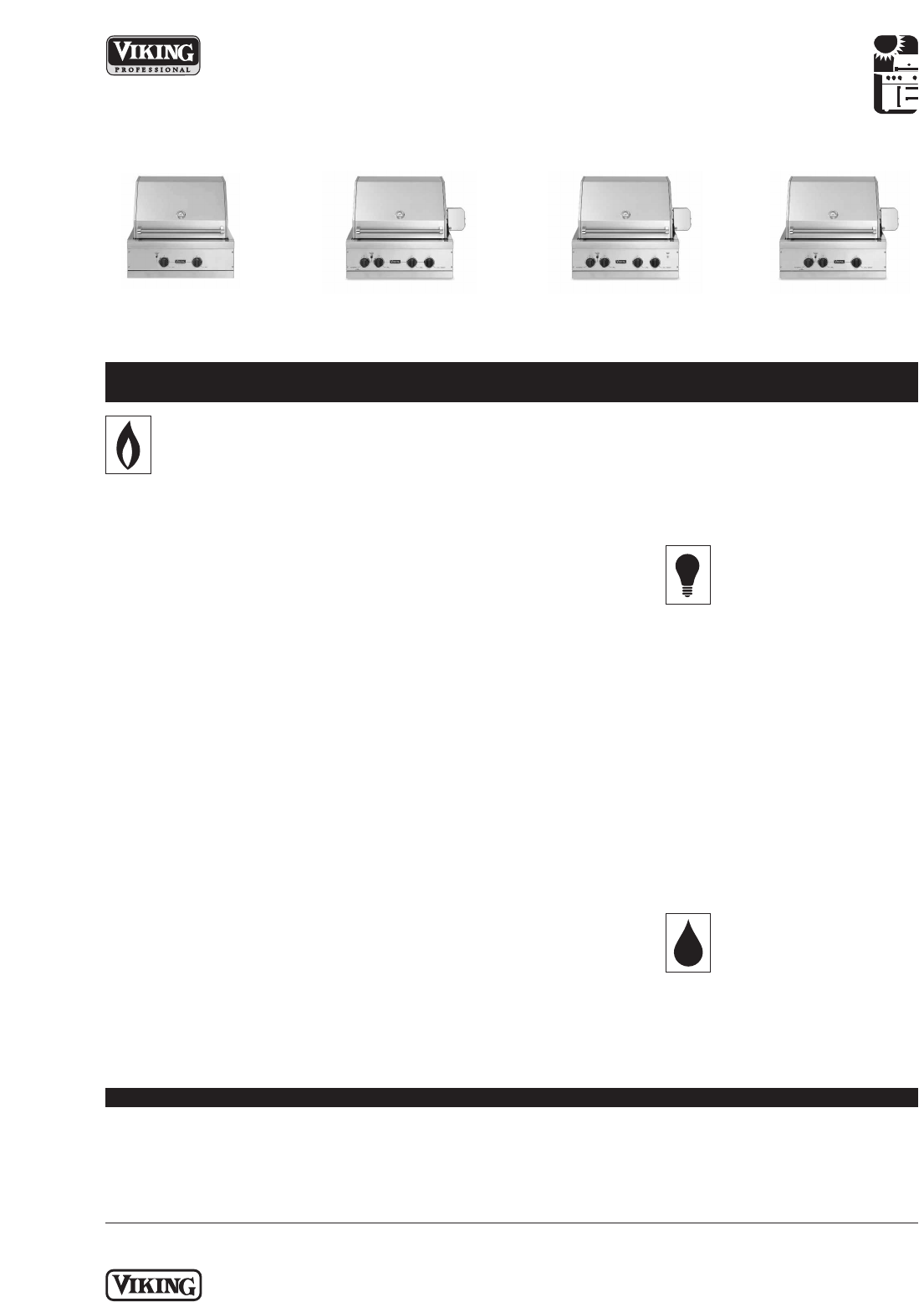
VGBQ030-2T
Premium T-Series
Two-Burner Grill
VGBQ300-2RT
Ultra-Premium T-Series
Two-Burner Grill
VGBQ300-2RE
Ultra-Premium E-Series
Two-Burner Grill
VGIQ300-2RT
Ultra-Premium T-Series
Two-Burner Grill w/TruSear