


Special offers from our partners!

Find Replacement BBQ Parts for 20,308 Models. Repair your BBQ today.
www.desatech.com
113111-01D
14
INSTALLATION
Continued
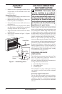
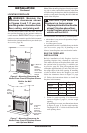
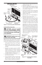
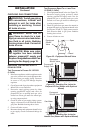
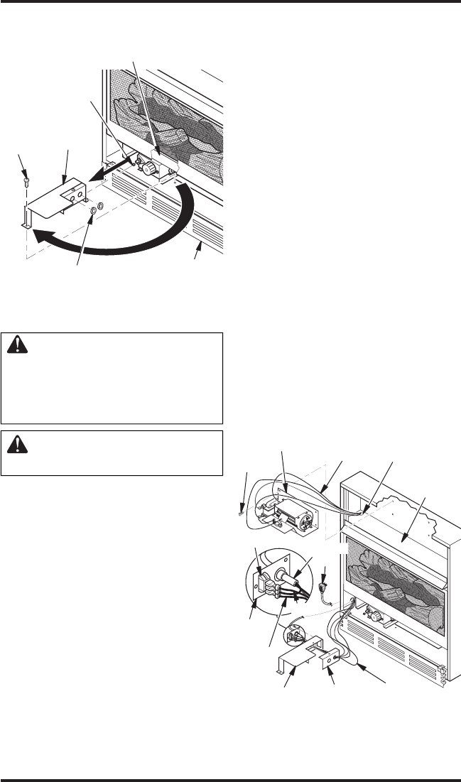
Figure 16 - Removing Valve Cover Shield
1
2
Remove
Screw
Valve
Cover
Shield
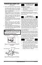
Shoulder
Screw
Branch Support
Snap Bushings
Bottom Louver
Assembly
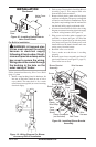
sembly to the outer casing with 4 #10 screws
provided (see Figure 17).
6. Route the wire harness through the hole in
left side of baffle. Pull wire harness through
lower opening above where the valve shield
was removed (see Figure 17).
7. Insert the 4 wire harness into one of the round
holes in the rear of the valve cover shield and
through the rectangular hole in the front of
shield (see Figure 17).
8. Reconnect red wire to switch position 3.
Reconnect blue wire to switch position 1.
Reconnect green and white wires.
9. Install the switch plate on the valve cover
shield with 2 #10 screws provided (see Figure
17). Reinstall the valve cover shield. Route
power cord out of the cabinet by inserting
it through the bushing on the outer casing
(see Figure 17). Plug fan kit into 120-Volt
grounded power supply and test operation.
Note: When switch is in the AUTO position,
the fan will start after the heater has run for
a few moments. The fan will continue to run
for several moments after the heater has been
turned off. When switch is in the ON position,
the fan will run until turned to OFF. Reinstall
upper louver assembly and hood if previously
removed, (see Figure 15, page 13). Close
lower louver door.
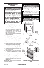
Installing Blower Assembly
CAUTION: Label all wires
prior to disconnection when
servicing controls. Wiring errors
can cause improper and danger-
ous operation.
CAUTION: Verify proper op-
eration after servicing.
Note: If you are using a mantel with your heater,
use the following instructions. If your heater is
built-in, see For Built-In Installation on page 15.
1. Install snap bushings found in hardware kit
into both holes in rear of valve cover shield.
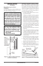
2. Make sure the wire harness is firmly con
-
nected to the terminals on the blower bracket
assembly.
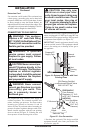
3. Note the wire locations on back of AUTO/
OFF/ON switch. The terminals on back of
switch are numbered 1, 2, and 3. Carefully
remove red wire from terminal 1 and blue
wire from terminal 3. Black wire can remain
on middle terminal 2 (see Figure 17).
4. Carefully disconnect green and white wires at
their insulated connectors.
5. In top of the heater cabinet, locate the four
mounting holes on the outer casing. Align
these four holes with those on the blower
bracket assembly. Attach blower bracket as
-
3
2
1
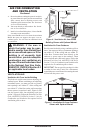
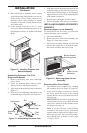
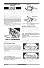
Figure 17 - Installing Blower Bracket
Assembly
Wire
Harness
Blower Bracket
Assembly
Screw
Valve Cover
Shield
Box Cover
Wire
Harness
Switch
Plate
Switch
Baffle
Wiring Routing
Hole in Baffle
Blue
Red
Power
Cord