


Special offers from our partners!

Find Replacement BBQ Parts for 20,308 Models. Repair your BBQ today.

www.desatech.com
113111-01D 13
INSTALLATION
Continued
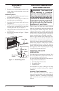
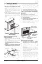
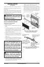
11. Place metal trim on shoulder screws located
on the side and top of the fireplace (see Assem
-
bling Perimeter Trim). Firmly snap trim over
shoulder screws. Align fireplace in mantel
assembly so the trim overlaps mantel evenly
on all three sides.
12. Lower bottom louver door. Use 3" wood
screws provided with mantel accessory to at
-
tach fireplace to base (see mantel instruction
sheet).
Side
Trim
Top Trim
Mitered Edge
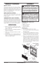
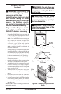
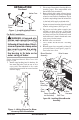
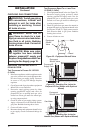
Figure 14 - Assembling Perimeter Trim
Shim
Set Screws
Adjusting
Plate
Slot
Slot
Assembling Perimeter Trim (Trim
Shipped with Mantel)
1. Remove packaging from three remaining
pieces of trim.
2. Locate two adjusting plates with set screws,
and two shims in the hardware packet.
3. Align shim under adjusting plate as shown in
Figure 14.
4. Slide one end of adjusting plate/shim in slot
on mitered edge of top trim (see Figure 14).
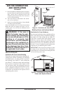
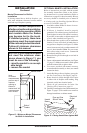
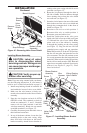
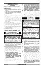
Figure 15 - Removing Upper Louver
Assembly
Upper Louver
Assembly
Black
Screws
Blower Bracket
Mounting Holes
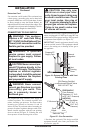
Removing Valve Cover Shield
1. Open bottom louver assembly by swinging
the assembly down (see Figure 16, page 14).
2. Using short Phillips screwdriver, remove
the screw under the center of the branch
support. Rotate valve cover shield clockwise
and slide out.
IMPORTANT: Do not remove shoulder screw
on the left side of valve cover shield. Slide the
valve cover shield off of the shoulder screw
(see Figure 16, page 14).
Note: If you do not have a short Phillips
screwdriver, the screen, log set, and branch
support must be removed so a longer screw
-
driver may be used. See Connecting Equip
-
ment Shutoff Valve to Heater Control, page
17, steps 1 and 2.
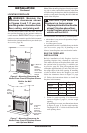
Figure 13 - Installing Fireplace into
Mantel Assembly
5. Slide other end of adjusting plate/shim in slot
on mitered edge of side trim (see Figure 14).
6. While firmly holding edges of trim together,
tighten both set screws on the adjusting plate
with slotted screwdriver.
7. Repeat steps 1 through 6 for other corner.
8. Set trim assembly aside for later installation.
INSTALLING BLOWER ACCESSORY
GA3450TA
Removing Upper Louver Assembly
To install the blower accessory, you must first
remove the upper louver assembly.
1. Lift screen off heater.
2. Remove 4 screws from louver assembly (see
Figure 15). Save these screws.
3. Pull louver assembly straight out from the
cabinet. Be careful not to scratch the paint.
Set louver assembly and screws aside.