


Special offers from our partners!

Find Replacement BBQ Parts for 20,308 Models. Repair your BBQ today.

Specifying Information—252
252-XX-0X
Model Activation Type Size
252 XX 0X
252—252 Series Valve 06—1” Electric
21—Normally Open Hydraulic
26—1
1
⁄2” or 2” Electric
4—1”
6—1
1
⁄2”
8—2”
Example: A 1
1
⁄2” electric 252 Series Valve,
would be specified as: 252-26-06
Specifi cations
Dimensions
• 1” – 6 ¾” H x 4 ½” W
• 1 ½” – 7 ¾” H x 6” W
• 2” – 9 ½” H x 7” W
Operating Specifi cations
• Recommended Flow Range:
– 1” – 5.0 to 20 GPM
– 1 ½” – 25 to 70 GPM
– 2” – 60 to 90 GPM
• Operating Pressure: 20 to 150 psi
• Solenoid: 24 VAC, 50/60 Hz
–Inrush: 0.30 amps, 7.20 VA
–Holding: 0.20 amps, 4.80 VA
• Burst pressure safety rating: 750 psi
Additional Features
• Globe and globe/angle built into one valve
• Manual flow control
• External manual bleed
• 24” lead wires (1 ½” and 2” electric) or
18” lead wires (1” electric)
• Self-cleaning, stainless steel metering pin
(electric)
• Tough, glass-filled bonnet
• Single-piece diaphragm
Options Available
• 89-7855 – Effluent Water Indicator Valve Flow
Control Knob
Warranty
• Two years
Female NPT In-line/Angle w/Flow Control
Model Description
• 252-06-04
• 252-26-06
• 252-26-08
• 252-21-06
• 252-21-08
1”
1½”
2”
1 ½” Normally Open
2” Normally Open
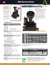
Globe and Angle
In One Valve
The all-in-one globe
and angle con-
figuration of the 252
Series valves allows
flexibility in design
and installation.
Angle installations
allow for less fric-
tion loss across the
piping system while
globe configura-
tions are standard
in many irrigation
systems.
External Bleed
The external bleed allows perfect
manual operation of the valve
without electrically charging the
solenoid. With the ability of
users to bleed the valve to atmo-
sphere, pressure is relieved and
the valve can effectively open
and close. System flushing can
also be accomplished using the
external bleed with debris and
other material being flushed out
of the port.
Note: DC Latching Solenoid not available.
www.toro.com • The Toro Company • Irrigation Division
5825 Jasmine St. • Riverside, CA • 92504 • 877-345-8676
Specifi cations subject to change without notice. For more information,
contact your local Toro distributor. P/N 09-1053-IRC
©2009 The Toro Company. All rights reserved.
Note: For optimum performance when designing a system, be sure to calculate total friction loss to
ensure sufficient downstream pressure.
For optimum regulation performance, size regulating valves toward the higher flow ranges. Flow rates are
recommended not to exceed 5 psi (0,3 bar) loss.
■
= Debris-resistant models
252 Series Friction Loss Data
Size Type
Config.
GPM Flow
5 10 20 25 30 40 50 60 70 80 100 120 150
1
½
"
Hydraulic
Globe
Angle
1.0
1.0
1.0
1.0
2.0
1.5
3.0
1.5
4.0
3.0
5.5
4.0
6.5
5.0
2"
Hydraulic
Globe
Angle
1.5
1.0
2.0
1.0
2.0
1.5
3.5
2.0
5.0
3.0
8.0
5.0
1"
Electric
Globe
Angle
3.0
2.0
4.0
3.5
5.0
4.5
6.0
4.5
7.0
5.0
9.5
7.5
1
½
"
Electric
Globe
Angle
1.5
1.5
1.0
1.0
2.0
1.5
3.0
2.0
4.0
3.0
5.0
3.0
7.0
5.0
2"
Electric
Globe
Angle
2.0
1.0
2.0
1.0
2.5
2.0
3.5
3.0
5.5
4.0
8.0
5.0
Water Management HighlightWater Management Highlight
252 Series Valves