


Special offers from our partners!

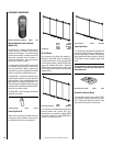
Find Replacement BBQ Parts for 20,308 Models. Repair your BBQ today.
15
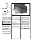
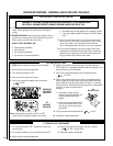
NOTE: DIAGRAMS & ILLUSTRATIONS NOT TO SCALE.
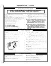
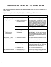
TROUBLESHOOTING THE ELECTRONIC IGNITION SYSTEM
N
ote: Before troubleshooting, be sure that the appliance main line gas shut-off valve, the gas control valve and the wall switch are in
the “ON” position.
Important: Valve system troubleshooting should only be accomplished by a qualified service technician.
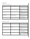
SYMPTOM POSSIBLE CAUSES CORRECTIVE ACTION
See Below.
Reset the limit switch button. If still not working, remove wire nut from the leads attached
to the limit switch and check for continuity. If no continuity, replace limit switch.
Disconnect the two black wires from the wire nuts. Test switch(s) for continuity with
a multimeter. If continuity is not indicated, switch(s) is defective and must be
replaced.
Note: Before replacing “OFF/ON” switch, be sure to check wiring for loose connec-
tions or broken wires and repair as needed.
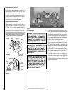
Check main burner orifice(s) for stoppage. Clean or replace.
Check vent system for obstructions.
A. Faulty Valve System.
B. Faulty limit switch.
C. “OFF/ON” or wall switch
defective.
A. Burner orifice plugged.
B. Obstructed vent system.
1. Burner will not light.
2. Burners come “ON” but
go “OFF.”
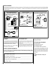
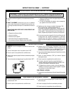
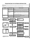
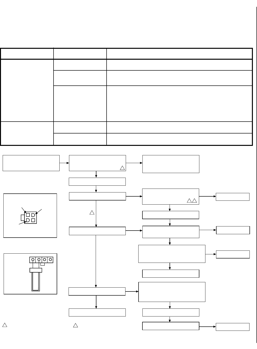
• Turn Off Gas Supply
• Assure Valve Switch Is In ON Position
• Disconnect Control Harness
• Set Thermostat To Call For Heat
• Check For Proper Voltage At Control Harness
(See Insert A). Voltage Should Be 24V
Between Thermostat Or Pressure Switch
And 24V Common And 24V Hot.
• Line Voltage Power
• Low Voltage Transformer
• Limit Controller
• Thermostat
• Wiring
2
CHECK
START
NO
• Plug Control Harness Into Valve. Wait For
Internal Check Delay.
YES
• Igniter Warms Up And Glows Red.
• With Pilot Burner Cable Connected, Measure
Voltage At Valve HSI Element Output. 24V
Nominal. (See Insert B)
NO
• Replace Igniter/Flame Rod Assembly.
YES
• Replace Valve.
NO
• Turn On Gas Supply. • Pilot Burner Lights.
• Check That Pilot Gas Is Flowing. Wait To
Assure Plot Gas Tubing Is Purged. Recycle
Call For Heat If Necessary.
NO
YES
NO
YES
YES
1
• Measure Voltage Between 24V Hot And 24V Common
Leads To Valve Control. Must Measure At Least 19.5
VAC With Igniter Powered (See Insert A). To Identify
Proper Lead, This Check Must Be Done With The
Valve Control Connected And Igniter Powered.
• Check Transformer And
Line Volt Supply.
NO
• Replace Pilot Assembly.
YES
• Check That Pilot Flame Makes Good Contact With
Pilot Burner Flame Rod.
• Check For Good Electrical Connection Through The
Pilot Tubing.
• If Both Of The Above Are Good, Replace Igniter/Flame
Rod Assembly.
• Cycle Thermostat Off And Back On.
YES
• Main Valve Opens And Main Burner Lights.
NO
YES
• System Is Okay.
YES
• Main Burner Lights.
NO
2
1
Igniter Will Cycle Off And Back On Once During
The 90 Second Ignition Trial. All Voltage
Measurements Must Be Taken While The Igniter
Is Powered.
When Measured Voltage At Connections, Use
Care To Assure Terminals Are Not Damaged.
• Replace Valve.
• Replace Valve.
24 Volt Hot
End View Of
Control Harness
Connector
24 Volt
Common
24 Volt
Switched
Check For Damaged Or Missing Terminals
In Connector
Insert A
Igniter Terminals
Insert B
2
1