


Special offers from our partners!

Find Replacement BBQ Parts for 20,308 Models. Repair your BBQ today.
8
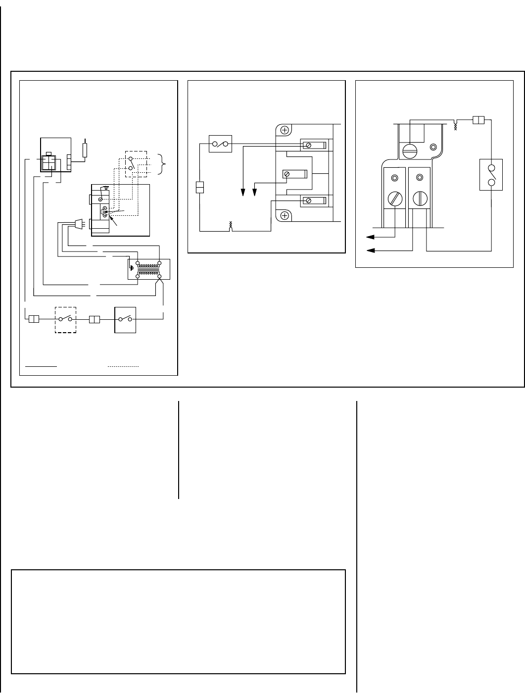
NOTE: DIAGRAMS & ILLUSTRATIONS NOT TO SCALE.
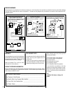
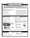
WIRING DIAGRAMS
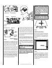
Wiring diagrams are provided here for reference purposes only. This information is also provided on schematics found on pullout labels attached
to the gas valve located within the control compartment. Two Millivolt wiring diagrams are provided here, one each for both Honeywell and SIT
equipped systems.
WARRANTY
Your gas appliance is covered by a limited twenty
year warranty. You will find a copy of the warranty
accompanying this manual. Please read the
warranty to be familiar with its coverage.
Retain this manual. File it with your other
documents for future reference.
REPLACEMENT PARTS
A complete parts list is found at the end of this
manual. Use only parts supplied from the
manufacturer.
Normally, all parts should be ordered through
your Lennox distributor or dealer. Parts will be
shipped at prevailing prices at time of order.
When ordering repair parts, always give the
following information:
1. The model number of the appliance.
2. The serial number of the appliance.
3. The part number.
4. The description of the part.
5. The quantity required.
6. The installation date of the appliance.
If you encounter any problems or have any
questions concerning the installation or appli-
cation of this system, please contact your dis-
tributor. For the name of your nearest distribu-
tor contact:
LHP
1110 West Taft Avenue • Orange, CA
92865
PRODUCT REFERENCE INFORMATION
We recommend that you record the following important information about your fireplace. Please
contact your Lennox dealer for any questions or concerns. For the number of your nearest Lennox
dealer, please call 800-731-8101
Your Fireplace's Model Number _______________________________________
Your Fireplace's Serial Number ________________________________________
The Date On Which Your Fireplace Was Installed __________________________
The Type of Gas Your Fireplace Uses ___________________________________
Your Dealer's Name_________________________________________________
1. If any of the original wire as supplied must be replaced,
1. it must be replaced with Type AWM 105°C – 18 GA.
wire.
2. 120V, 60Hz – Less than 3 amps.
BK
Junction Box
Transf.
120 V.
24 V
Factory Wired
Field Wired
BL
Electronic Wiring Diagram (Honeywell)
(Optional ON/OFF Switch Wiring)
R
BK
BL
To Opposite Side
G
W
OPT. ACCESSORY
SWITCH
120
VAC.
BK
LIMIT
SWITCH
W
Gas Valve
B
OPTIONAL
ON/OFF SWITCH
OR
WALL SWITCH
R
IGNITER
CONTROL
PILOT
ASSEMBLY
Break
Off Tab
BK
WHT
BK
BK
G
G
Thermopile
TH
TP
TH
TP
Honeywell Millivolt Wiring Diagram
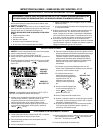
If any of the original wire as supplied must be replaced,
it must be replaced with Type AWM 105°C – 18 GA. wire.
TH
TPTH
TP
* For Wall Switch Attachment Only.
*
Limit
Switch
BK
WHT
BK
BK
SIT Millivolt Wiring Diagram
* For Wall Switch Attachment Only.
If any of the original wire as supplied must be replaced, it
must be replaced with Type AWM 105°C – 18 GA. wire.
Thermopile
TH
TP
TH
TP
Limit Switch
BK
BK
BK
WHT
*