


Special offers from our partners!

Find Replacement BBQ Parts for 20,308 Models. Repair your BBQ today.
Micrologic™ 2.0A, 3.0A, 5.0A, and 6.0A Electronic Trip Units 48049-136-05
Section 4—Trip Unit Replacement Rev. 01, 07/2012
© 1999–2012 Schneider Electric All Rights Reserved30-EN
ENGLISH
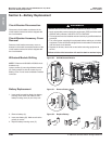
Trip Unit Installation
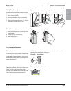
1. Inspect trip unit connector pins and surfaces.
If there is any damage, misaligned pins, or
contamination, stop installation and contact
the local sales office for factory authorized
service.
2. Inspect trip unit mounting base on the circuit
breaker. Clear any debris from area and
check that all accessory wiring is properly
routed for the trip unit being installed. If there
is any damage or contamination, stop
installation and contact the local sales office
for factory authorized service.
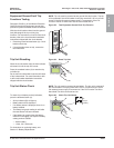
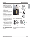
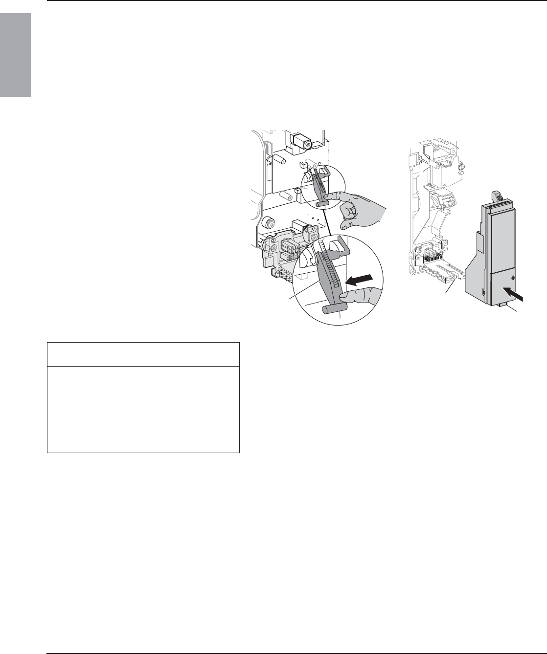
3. For Masterpact NW circuit breaker only:
Manually depress trip unit interlock (A) and
hold it in place during steps 4–6 below.
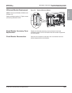
4. Align guide rail (B) on bottom of trip unit with
guide rail slot (C) on trip unit mounting base
in circuit breaker and gently slide the trip unit
in until it stops.
NOTE: The Masterpact NT and NW trip unit
mounting bases are shock mounted and
therefore can flex slightly.
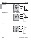
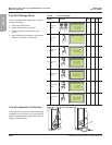
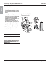
Figure 45: Install Trip Unit
06135453
06135451
Masterpact NW Circuit Breaker
A
C
B
NOTICE
HAZARD OF EQUIPMENT DAMAGE
Check installation of trip unit to assure proper
connections and seating.
Failure to follow this instruction can result
in equipment damage or improper circuit
breaker tripping.