


Special offers from our partners!

Find Replacement BBQ Parts for 20,308 Models. Repair your BBQ today.
5
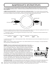
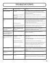
Do not use a flame to leak test.
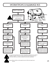
LEAK TESTING: This must be done before initial use, annually and whenever any gas components are replaced or serviced. No
smoking while performing this test, and remove all sources of ignition. See
Leak Testing Diagram
for areas to check.
1. Turn all burners controls to off. Turn supply valve on.
2. Brush a half and half solution of liquid soap and water onto all joints and connections of the regulator, hose, manifolds and valves.
3. Bubbles will indicate a gas leak. Either tighten the loose joint or replace the part with one recommended by the dealer.
4. If the leak cannot be stopped, shut off the gas supply, disconnect it and have the barbecue inspected by your gas supplier or dealer.
Do not use the appliance until the leak has been corrected.
5. Turn off gas supply.
GAS HOOK-UP INSTRUCTIONS
CYLINDER CONNECTION: Ensure that the gas regulator hose is kink free. Remove the cap or plug from the cylinder fuel valve.
Insert the black QCC1 regulator nipple onto the QCC1 fuel valve. Hand tighten clockwise.
Do not use tools. Leak test all joints prior to
using the barbecue.
A leak test must be performed annually, and each time a cylinder is hooked up, or if a part of the gas system is
replaced.
PROPANE CYLINDER INSTALLATION: Set cylinder into the groove of the lower tank mounting bracket. Ensure that tank
valve faces away from the barbecue. Lower the top tank mounting bracket onto the cylinder and tighten with wing nut.
IMPORTANT: Ensure that the hose is routed around the front side of the cart leg to maintain proper clearance to the
underside of the unit.
NATURAL GAS HOOK-UP: This natural gas grill is supplied with a 10ft supply hose (complete with a quick disconnect) designed for
natural gas and certified for outdoor use. The gas grill is designed to operate at an inlet pressure of 7 inches water column. A regulator
must be installed if the house pressure is greater than 7 inches water column. Piping and valves upstream of the quick disconnect are not
supplied.
The quick disconnect must not be installed in an upward direction and a readily accessible manual shut-off valve must be installed upstream
of, and as close to, the quick disconnect as is feasible. The flared end of the hose must be connected to the unit as illustrated in the
Natural
Gas HoseAttachment
diagram. These connections must be made by a licensed gas installer. Leak test all joints prior to using the gas grill.
IMPORTANT: Ensure that the hose is routed around the front side of the cart leg to maintain proper clearance to the
underside of the unit.
NON-SIDE BURNER UNITS: Connect the flared end of the hose to the fitting on the end of the manifold tube. Wrench tighten. (
Do not
use thread sealer/pipe dope.)
SIDE BURNER UNITS: Connect the 20" hose from the manifold, to the side burner as illustrated in the
Natural Gas Hose Attachment
diagram. Connect the supply hose to the flare connection which faces down from the side burner. Tighten all connections using two
wrenches. (
Do not use thread sealer/pipe dope.)
LEAK TESTING INSTRUCTIONS