


Special offers from our partners!

Find Replacement BBQ Parts for 20,308 Models. Repair your BBQ today.
10
W415-0377 / 03.04.03
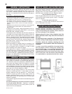
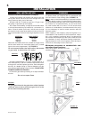
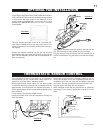
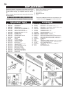
Attach the connectors from the black and white wires to the
thermodisc and secure the thermodisc bracket to the secur-
ing stud at the bottom left of the unit using a lock washer and
wing nut. Ensure that the thermodisc touches the firebox
wall.
Attach the connectors from the black and red wires to the
blower.
Attach and secure the variable speed switch using the nut
provided. Plug the harness cord into the receptacle.
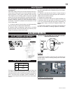
The wire harness provided in this kit is a universal
harness. When installed, ensure that any excess
wire is contained, preventing it from making con-
tact with moving or hot objects.
Because the blower is thermally activated, when
turned on, it will automatically start approximately
15 minutes after lighting the fireplace and will run
for approximately 30-45 minutes after the fireplace
has been turned off. Use of the fan increases the
output of heat.
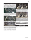
Drywall dust will penetrate into the blower bear-
ings causing irreparable damage. Care must be
taken to prevent drywall dust from coming into
contact with the blower or its compartment. Any
damage resulting from this condition is not cov-
ered by the warranty policy.
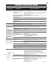
INSTALLATION TO BE DONE BY A QUALIFIED INSTALLER
and must be electrically connected and grounded in accord-
ance with local codes. In the absence of local codes, use the
current CSA C22.1 CANADIAN ELECTRICAL CODE in Canada or the
ANSI/NFPA 70 NATIONAL ELECTRICAL CODE in the United States.
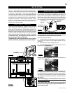
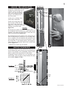
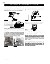
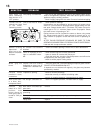
The three slots allow ease
of adjustment of the blower.
For a quiet running blower,
do not allow the assembly
to sit on the firebox base.
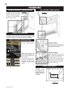
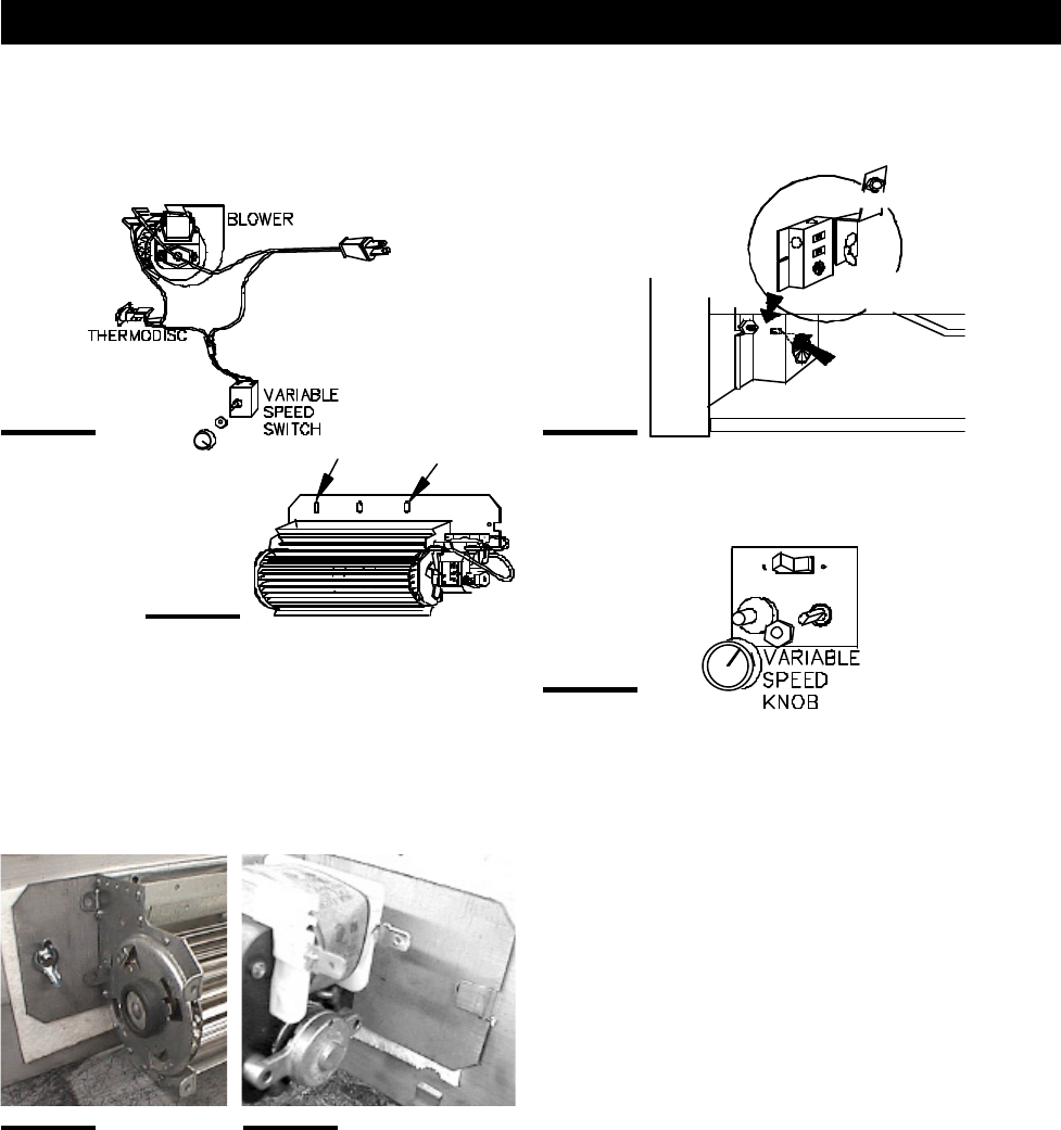
Slide the vibration reducing pad (A) into the clip and onto
the threaded stud (B) at the other end, piercing a hole into
the pad. The blower must be able to be positioned entirely
onto the pad.
Tilt the blower onto its side. Slide it past the controls and
into the clip (C). Secure to the threaded stud using the lock
washer and wing nut provided. Ensure that the blower
does not touch the fireplace base or the firebox.
red
white
black
THERMODISC
GROUND
SCREW
JUNCTION
RECEPTACLE /
BOX
ADJUSTMENT
SLOTS
FIGURE 20
FIGURE 21
FIGURE 22 FIGURE 23
FIGURE 25
C
A
B
FIGURE 24
OPTIONAL BLOWER INSTALLATION