


Special offers from our partners!

Find Replacement BBQ Parts for 20,308 Models. Repair your BBQ today.

8
NOTE: DIAGRAMS AND ILLUSTRATIONS ARE NOT TO SCALE.
Any outside air ducts and/or ash dumps in the fireplace shall be perma-
nently closed at time of appliance installation.
A qualified gas appliance installer must install this dual-listed appli
-
ance.
Check gas type: The gas supply must be the same as stated on the
appliance’s rating plate. If the gas supply is different, DO NOT INSTALL
the appliance. Contact your dealer for the correct model.
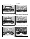
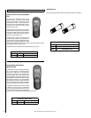
Step 1. Unpack Appliance - Remove appliance from carton. Cut tie-wires
holding ember bed rear log to the base. Unwrap foam packaging from
ember bed rear log.
Step 2. Place Ember Bed Rear Log – Place the ember bed rear log with
ember chunks facing the front of the appliance such that the middle grate
bar aligns with the notch in the top of the ember piece. Push the ember
bed rear log toward the front of the unit until it touches the lip on the
base and cannot go any further.
Step 3. Placement of Appliance – Center the appliance in the fireplace
or firebox. Make certain the grate front feet sit inside the front edge of
the fireplace or firebox, and that there is adequate clearance around the
appliance for access and operation.
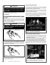
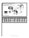
Step 4. Connecting Gas Line – A qualified gas appliance installer must
connect the dual-listed gas appliance to the gas supply.
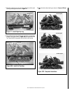
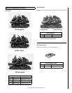
Step 5. Place Logs – See log placement on Page 10.
Consult all local codes.
Route gas line using techniques and materials prescribed by local
and/or national codes. Only use 1/2" or greater pipe size to allow full gas
volume to the gas fireplace. Undue pressure loss will occur if the pipe
is too small.
An ANSI approved manual shut-off valve and union must be installed upstream
of the appliance within the fireplace cavity when rigid pipe is used.
IMPORTANT: HOLD APPLIANCE REGULATOR WITH A WRENCH TO
PREVENT MOVEMENT WHEN CONNECTING TO INLET PIPING
An external regulator must be used on all propane (L.P.G.) appliances,
in addition to the regulator fitted to the appliance, to reduce the supply
tank pressure to 13" W.C. (maximum).
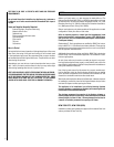
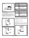
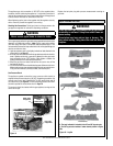
Example: The bottom of the mantel may project from the wall a maxi-
mum of 2-1/2" at a minimum of 8" above the opening. The top shelf of
the mantel may project a maximum of 6" at a minimum of 14-1/2" above
the opening.
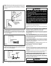
The appliance base may be lower than 5" above the combustible flooring
materials if the combustible flooring materials are more than 14" from the
fireplace or firebox opening (Figure 8).
Step 5. Floor clearance: If combustible flooring materials, such as carpet-
ing or asphalt tile, are to be located within 14" of the fireplace or firebox
opening, the appliance base must be at least 5" above the combustible
flooring material (Figure 7).
Noncombustible
Material
14-1/2"
18-5/8”
22-1/2"
26"
10"
2-1/2"
6"
8"
12"
8"
Min.
Hood (Canopy)
Combustible Flooring
Material
5" Min.
Combustible
Flooring
Material
Can be less
than 5"
14" Min.
Figure 8
Figure 7
Figure 6
INSTALLATION
WARNINGS
• Do not use a blower insert, heat exchanger
insert or other accessory not approved
for use with this heater.
• Installed decorative glass door enclosures must be
fully opened when operating this dual-listed gas
appliance.
• Special care is required if you are installing the unit
into a sunken fireplace. You must raise the fireplace
floor to allow access to gas log controls. This will
ensure adequate air flow and guard against soot-
ing. Raise the fireplace floor using noncombustible
materials.
WARNING
Connecting directly to an unregulated propane tank may
cause an explosion.