


Special offers from our partners!

Find Replacement BBQ Parts for 20,308 Models. Repair your BBQ today.
ASSEMBLY INSTRUCTIONS
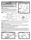
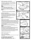
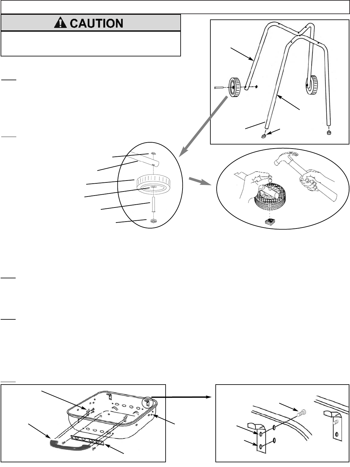
STEP 1. Front Leg Assembly
Install Leg Caps (13) on ends of Front Leg (2) (FIG. 1).
Note: The Front Leg does not have holes at the end near the Leg Caps
STEP 2. Wheel Leg Assembly
Lay the Wheel Leg (3) on its side on a hard floor or surface. Insert
Wheel Axle Rivet (16) through outer recessed hub of Wheel (6) and
through Wheel Leg (FIG. 2). Place Wood Anvil (14) under center of
Wheel Axle Rivet and Wheel hub. Drive the Axle Pushnut (15) (FIG. 3)
onto Wheel Axle Rivet. Repeat for the other side of Wheel Leg.
Note:
The Wheel Leg (3) has holes at the end of the tubes, and is
shorter than Front Leg (2).
Front Leg
Wheel Leg
Axle Pushnut
Wheel Leg
Wheel
Wheel Axle Rivet
Wood Anvil
FIG. 1
FIG. 2
FIG. 3
recessed hub of Wheel
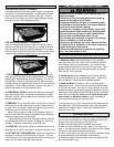
STEP 3. Slide Vent Assembly
Insert 10-24x1/2” Bolt (22) through the slot in the Slide Vent (9) and through the hole in the Bowl (4). Attach a Square Nut
(20) to the Bolt but do not tighten completely (FIG. 4). Attach Bolt (22) and Square Nut (20) on the other end of the Slide
Vent to the Bowl.
Repeat for the second Slide Vent on the opposite side of the Bowl. Square Nuts should be on the inside of the Bowl.
Note:
Tighten Bolts and Square Nuts but make sure Slide Vents move easily from side-to-side.
STEP 4. Rear Grid Bracket Assembly
With the hinge holes in bowl toward the back, align bottom dimple and upper hole of Rear Grid Bracket (10) with holes
inside Bowl (4) in the bowl back. Insert #8 Screw (21) through the upper hole of Bowl and Rear Grid Bracket (FIG 4 and
FIG. 5). Tighten screw into bracket. Repeat for second Rear Grid Bracket
Note:
Rear Grid Brackets have one hole and one indented dimple each.
STEP 5. Bowl Handle and Front Grid Bracket Assembly
Align two holes in the Front Grid Bracket (11) with the holes inside the Bowl (4) in the bowl front (FIG 4). Align the Bowl
Handle (7) with the same two holes. Insert #10-16 x 5/8” Screw (19) through the top hole of the Front Grid Bracket, through
the Bowl, and into the top hole of the Bowl Handle. Do not tight completely. Insert a second screw into the bottom hole of the
Front Grid Bracket, through the bottom hole of the Bowl and into the bottom hole of the Bowl Handle. Do not tighten.
Repeat for second Front Grid Bracket to mount the Bowl Handle and both front brackets. Tighten completely, but do not over
tighten or cross-thread.
Note:
Front Grid Brackets have two holes in each.
FIG. 4
FIG. 5
Rear Grid Brackets
Front Grid
Bracket
Bowl
Handle
4
Bowl Front
Bowl Back
Align hinge
holes to the
back.
Slide Vent
Hole
Indented
dimple
No holes
at bottom
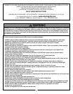
To reduce the risk of a cut, pinch, or other bodily injury:
• Wear protective gloves when handling or
assembling parts that could have sharp edges.
Leg Cap
3/8 Screw