


Special offers from our partners!

Find Replacement BBQ Parts for 20,308 Models. Repair your BBQ today.
9
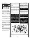
NOTE: DIAGRAMS & ILLUSTRATIONS NOT TO SCALE.
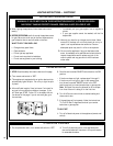
WARRANTY
Your gas appliance is covered by a limited
twenty year warranty. You will find a copy of
the warranty accompanying this manual.
Please read the warranty to be familiar with its
coverage.
Retain this manual. File it with your other
documents for future reference.
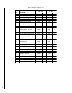
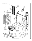
REPLACEMENT PARTS
A complete parts list is found at the end of this
manual. Use only parts supplied from the
manufacturer.
Normally, all parts should be ordered through
your Lennox distributor or dealer. Parts will be
shipped at prevailing prices at time of order.
If you encounter any problems or have any
questions concerning the installation or appli-
cation of this system, please contact your dis-
tributor, or Lennox directly:
LENNOX HEARTH PRODUCTS
1110 West Taft Avenue
Orange, CA 92865
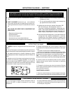
PRODUCT REFERENCE INFORMATION
We recommend that you record the following important information about your fireplace. Please
contact your Lennox dealer for any questions or concerns. For the number of your nearest Lennox
dealer, please call 1-800-9-LENNOX.
Your Fireplace's Model Number _______________________________________
Your Fireplace's Serial Number ________________________________________
The Date On Which Your Fireplace Was Installed __________________________
The Type of Gas Your Fireplace Uses ___________________________________
Your Dealer's Name_________________________________________________
When ordering repair parts, always give the
following information:
1. The model number of the appliance.
2. The serial number of the appliance.
3. The part number.
4. The description of the part.
5. The quantity required.
6. The installation date of the appliance.
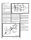
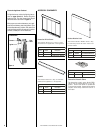
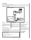
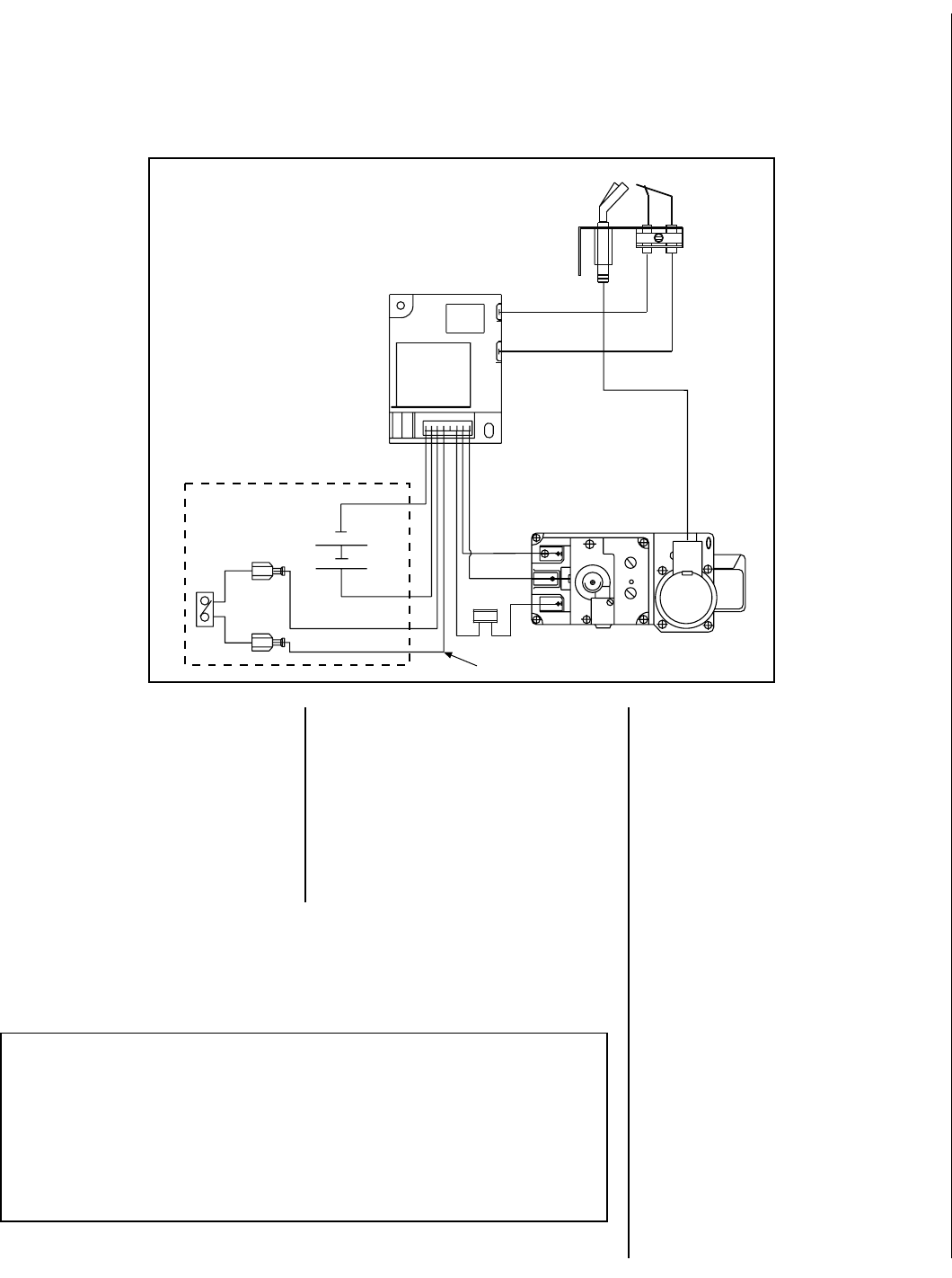
WIRING DIAGRAMS
Wiring diagrams are provided here for reference purposes only. This information is also provided on schematics attached directly to the appliance
on a pullout panel located within the control compartment.
CAUTION: LABEL ALL WIRES PRIOR TO DISCONNECTION WHEN SERVICING CONTROLS. WIRING ERRORS CAN CAUSE IMPROPER AND
DANGEROUS APPLIANCE OPERATION.
INTERMITTENT ELECTRONIC WIRING DIAGRAM
BROWN
BROWN
BLACK
BATTERY
WALL SWITCH BOX
BLACK (SENSOR)
BLACK (IGNITOR)
SPARK TO PILOT IGNITOR
IGNITOR MODULE
3V
RED
PI LO T
IN
OUT
VEN T
LO
HI
TH
TP
TH
TP
IN
ORANGE (THTP)
BLACK (TP)
GREEN (TH)
LIMIT
SWITCH
UMBILICAL CORD (9 Feet)