


Special offers from our partners!

Find Replacement BBQ Parts for 20,308 Models. Repair your BBQ today.

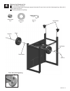
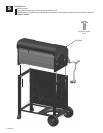
10
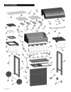
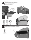
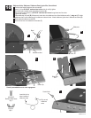
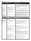
Sideburner Valve, Sideburner, Sideburner Bezel, Control Knob
Ignitor Wire,
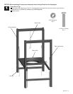
Position valve behind fascia and line up holes (A).
Insert (1) of the #8-32x3/8” stainless steel screws, but do not fully tighten.
Slip bezel under inserted screw and position as shown (A).
Line up other hole and insert (1) #8-32x3/8” through bezel and into valve.
Tighten both securely.
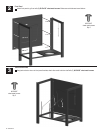
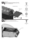
Place sideburner into shelf (B). Make sure valve into sideburner tube. Attach sideburner with (1) wing nut ( C). Under
sideburner shelf, install sideburner clip to sideburner tube and valve. Attach sideburner ignitor wire to electrode as shown (D).
Place grate onto sideburner shelf (E).
Press control knob onto sideburner valve stem (F).
stainless steel screw
to insert
Wing Nut
Qty. 1
#8-32X3/8”
S Screw
Qty. 2
tainless Steel
464220110 • 19
Clip around
sideburner
valve
Insert this tip into
hole in bottom of
sideburner tube
A
Bezel
B
C
Sideburner
Side Burner Tube
Valve
Ignitor wire
Burner Clip
D
Sideburner
Grid
Control Knob
Correctly assembled burner-to-valve engagement
E
F
Sideburner Valve
Sideburner Valve
Wing Nut