


Special offers from our partners!

Find Replacement BBQ Parts for 20,308 Models. Repair your BBQ today.
CQ8000A UNIVERSAL HOT SURFACE IGNITER KIT
69-2460EFS—03 2
NOTE: If there is an orange rubber gasket on the original
metal bracket, carefully remove the gasket from the
original bracket and use it with the CQ8000A bracket
E to support the replacement.
Select the proper CQ8000A bracket
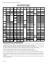
1. Use the cross-reference table to determine which igniter
models are recommended for replacement. See Table 1
on page 4.
2.
Using the bracket selection templates (Fig. 1 and Fig. 2),
the cross-reference (Table 1), and the original igniter
assembly, place the igniter on the templates to confirm
which bracket to use for this installation.
NOTES:
1. Each of the six brackets has a letter stamped on it
(A through E) for easy identification.
2. If bracket A is selected, use pliers to remove
either Tab 1 or Tab 2 at the score line per the
bracket template directions.
3. If bracket E is selected, ensure that the original
orange gasket (if present) is reused.
3.
Install the Universal igniter into the selected bracket using
the provided thread forming screw.
NOTE: In some appliance applications, installation may be
easier if the bracket is installed in the appliance first,
then the igniter added to the bracket. As the thread
forming screw for the bracket takes some force for ini-
tial tightening, start the screw in the bracket to set the
threads, remove the screw, attach the bracket to the
appliance using the original screw(s), and then attach
the igniter and its thread forming screw to the bracket.
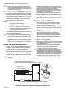
Install the replacement igniter
1. Carefully position the replacement igniter and bracket
assembly into the appliance. Position the assembly so
the existing mounting screw holes align with the mount-
ing holes or slots in the replacement assembly.
2.
Secure the replacement igniter bracket with the original
igniter screws. The CQ8000A brackets are designed with
the capability to make minor adjustments in the igniter
location. Use care to adjust the igniter hot spot to a posi-
tion where it will light reliably.
NOTE: In some applications, a shorter screw may simplify
installation.
3.
Orient the replacement igniter the same way as the origi-
nal igniter was positioned and secure it. Be sure the igniter
portion does not touch the appliance or burners.
4.
Carefully route the replacement igniter lead wires away
from the burner flame and any moving parts on the com-
bustion air blower in the appliance.
5.
Locate the appliance igniter wiring harness. Clip off the
connector and strip both wires to 1/4 in. (6 mm).
6.
Use the provided wire nuts to attach the igniter lead wires
to the appliance wiring harness. The igniter lead wires can
be cut shorter if desired. Strip them to 1/4 in. (6 mm) prior
to attaching to the appliance wire harness.
Check out the installation
1. Recheck location of the igniter bracket assembly and
lead wires to assure there is no interference and that
the lead wires will not be exposed to excessive heat or
moving parts when the appliance is firing.
2.
Recheck the line voltage connections between the igniter
harness and the appliance wiring harness to be sure they
are secure. Assure that no bare wire is exposed at this
connection.
3.
Turn the electrical power supply on, but leave the gas
supply off, and initiate a light off (call for heat) cycle.
Observe the hot surface igniter during the sequence to
confirm it gets hot and that there is sufficient clearance
between the igniter and other appliance parts. Also
confirm that the lead wire routing does not interfere with
appliance operation.
4.
Remove the call for heat signal.
5.
Turn the gas supply on.
6.
Initiate a call for heat. Observe the light off sequence and
confirm that the appliance lights properly and stays lit once
the actual gas flow starts.
7.
If the appliance lights and the main flame stays stable,
remove the call for heat and allow the shut down
sequence to be completed. Repeat step 6 two more times
to assure the light off of the appliance is reliable.
8.
If the appliance does not light properly, it may be neces-
sary to adjust the location of the hot surface igniter. Each
CQ8000A bracket is designed to allow some adjustment of
the igniter location in the appliance. Turn the gas supply off
then loosen the mounting screw(s) and make adjustments.
Retighten the screw(s) and repeat from step 5. It may be
necessary to repeat this process a few times in order to
determine a position where the igniter will light reliably.
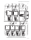
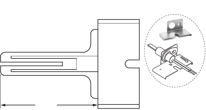
Fig. 1. Igniter bracket B template; dimensions in in. (mm).
Modèle de support d'allumeur B; dimensions en pouces (mm).
Plantilla del soporte B del encendedor; dimensiones en pulgadas (mm).
PLACE REMOVED IGNITER OVER TEMPLATE OUTLINE
PLACER L’ALLUMEUR RETIRÉ SUR LE TRACÉ DU MODÈLE
COLOQUE EL ENCENDEDOR EXTRAÍDO SOBRE EL CONTORNO DE LA PLANTILLA
MFS28764
USE BRACKET B
UTILISER LE SUPPORT B
UTILICE EL SOPORTE B
2-3/16 (56)
B
BRACKET B
SUPPORT B
SOPORTE B