


Special offers from our partners!

Find Replacement BBQ Parts for 20,308 Models. Repair your BBQ today.

6 4036-903 Rev C 01/04
OGL-42 INSTALLATION INSTRUCTIONS
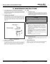
1. Gas Line and Valve Assembly Installation
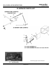
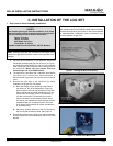
Figure 1 - Placing the Burner Assembly
Note: Have the gas supply line installed in accordance
with building codes by a qualified installer approved and/or
licensed as required by the locality. In the Commonwealth
of Massachusetts, installation must be performed by a
licensed plumber or gas fitter.
a. Place the burner assembly in the appliance, hand-bend
the flexible stainless steel gas line as shown in Figure 1
and feed the thermocouple line, pilot line and stainless
steel flexible gas line through the hole in the right side of
the appliance. Make sure the excess pilot and
thermocouple line is OUTSIDE the box.
b. The appliance is provided with a stainless steel flexible
connector and a listed (and Commonwealth of
Massachusetts approved) tee-handle manual shutoff
valve.
c. Remove the right side of the valve box for easier
installation of the gas line. Set aside.
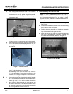
1) Bend the flanges of the remaining three sides of
the valve box 90° at the perforations (Figure 2),
place a bead of silicone (not provided) on the back
side of the flanges and slide the valve box into the
square hole on the side of the FPS enclosure. (If
you are not using an FPS enclosure, the valve
must be located in an accessible position where
one person can operate the valve and light the pilot
simultaneously.) All connections within the enclo-
sure need to be accessible for future maintenance
or troubleshooting.
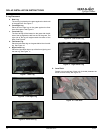
2) Secure the 3-sided valve box to the FPS enclosure
with the drywall screws provided. See Figure3.
d. Remove the valve from the valve box for ease of assembly
by removing the two screws holding the valve to the valve
bracket.
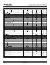
SAFETY:
This outdoor gas log set must be installed in a UL-listed
outdoor fireplace that has a gas knockout on the right side
with the following minimum firebox dimensions:
Depth: 19 inches
Height: 23 inches
Rear Width: 23 inches
Front Width: 42 inches
Suitable fireplaces would be STS42, OUT42, Montana.
Figure 3 - Secure Valve Box to FPS
Figure 2 - Remove Right Side of Valve Box & Bend Flanges
C. INSTALLATION OF THE LOG SET
Note: Although knockouts are provided on both sides of the
fireplace, the gas inlet should be routed to the right side of the
fireplace.