


Special offers from our partners!

Find Replacement BBQ Parts for 20,308 Models. Repair your BBQ today.

Heat-N-Glo Lifestyle Collection • Dakota 42/Dakota 42H • 4036-905 Rev I • 10/05 21
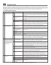
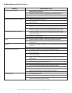
With proper installation, operation and maintenance your gas appliance will provide years of trouble-free service. If you do
experience a problem, this troubleshooting guide will assist a qualifi ed service person in the diagnosis of a problem and the
corrective action to be taken. This troubleshooting guide can only be used by a qualifi ed service technician.
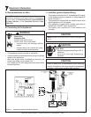
A. Intellifi re Ignition System
11
Troubleshooting
Symptom Possible Causes Corrective Actions
1. The ignitor/module makes
noise, but no spark.
A. Incorrect wiring. Verify “S” wire (white) for sensor and “I” wire (orange) for ignitor are connected to the
correct terminals on the module and the pilot assembly. Reversed wires at the module
may cause the system to make a sparking noise, but the spark may not be present at
pilot hood.
B. Loose connections or
electrical shorts in the
wiring.
Verify there are no loose connections or electrical shorts in wiring from module to
pilot assembly. The rod closest to the pilot hood should be ignitor. Verify connections
underneath pilot assembly are tight; also verify the connections are not grounding out
to the metal chassis, pilot burner, pilot enclosure, mesh screen if present, or any other
metal object.
C. Ignitor gap is too large. Verify gap of ignitor to pilot hood. The gap should be approximately .17 in. or 1/8 in.
D. Faulty module. Turn ON/OFF rocker switch or wall switch to OFF position. Remove ignitor wire “I”
from module. Place ON/OFF rocker switch or wall switch in ON position. Hold ground
wire about 3/16 in. away from “I” terminal on module. If there is no spark at “I” terminal,
module must be replaced. If there is a spark at “I” terminal, module is fi ne. Inspect pilot
assembly for shorted sparker wire or cracked insulator around electrode.
2. Pilots won’t light, there is
no noise or spark.
A. Transformer installed
incorrectly.
Verify that transformer is installed and plugged into module. Check voltage of
transformer under load at space connection on module with ON/OFF switch in ON
position. Acceptable readings of a good transformer are between 3.2 and 2.8 volts AC.
B. A shorted or loose
connection in wiring
confi guration or wiring
harness.
Remove and reinstall the wiring harness that plugs into module. Verify there is a tight
fi t. Verify pilot assembly wiring to module. Remove and verify continuity of each wire in
wiring harness.
C. Improper wall switch
wiring.
Verify wall switch is wired correctly.
D. Module not grounded. Verify black ground wire from module wire harness is grounded to metal chassis of
appliance.
E. Faulty module. Turn ON/OFF rocker switch or wall switch to OFF position. Remove ignitor wire “I”
from module. Place ON/OFF rocker switch or wall switch in ON position. Hold ground
wire about 3/16 in. away from “I” terminal on module. If there is no spark at “I” terminal
module must be replaced. If there is a spark at “I” terminal, module is fi ne. Inspect pilot
assembly for shorted sparker wire or cracked insulator around electrode.
3. Pilot lights but continues
to spark, and main burner
will not ignite. (If the pilot
continues to spark after
the pilot fl ame has been
lit, fl ame rectifi cation has
not occurred.)
A. A shorted or loose
connection in sensor rod.
Verify all connections to wiring diagram in manual. Verify connections underneath pilot
assembly are tight. Verify connections are not grounding out to metal chassis, pilot
burner, pilot enclosure or screen if present, or any other metal object.
B. Poor fl ame rectifi cation or
contaminated sensor rod.
Verify fl ame is engulfi ng sensor rod. If the pilot assembly does not have a ground
strap, consider installing one to increase fl ame rectifi cation. Verify correct pilot orifi ce
is installed and inlet gas specifi cations are met. Flame carries rectifi cation current, not
the gas. If fl ame lifts from pilot hood, the circuit is broken. A wrong orifi ce or too high
an inlet pressure can cause pilot fl ame to lift. The sensor rod may be contaminated.
Clean sensor rod with emery cloth.
C. Module is not grounded. Verify that module is securely grounded to metal chassis of appliance. Verify that the
wire harness is fi rmly connected to module.
D. Damaged pilot assembly
or dirty sensor rod.
Verify that ceramic insulator around the sensor rod is not cracked, damaged, or loose.
Verify connection from sensor rod to white sensor wire. Clean sensor rod with emery
cloth to remove any contaminants that may have accumulated on sensor rod. Verify
continuity with a multimeter with ohms set at lowest range.
E. Faulty module. Turn ON/OFF rocker switch or wall switch to OFF position. Remove ignitor wire “I”
from module. Place ON/OFF rocker switch or wall switch in ON position. Hold ground
wire about 3/16 in. away from “I” terminal on module. If there is no spark at “I”
terminal, module must be replaced. If there is a spark at “I” terminal, module is fi ne.
Inspect pilot assembly for shorted sparker wire or cracked insulator around electrode.
4. Pilot sparks, but pilot will
not light.
A. Correct gas supply. Verify that incoming gas line ball valve is “open”. Verify that inlet pressure reading is
within acceptable limits, inlet pressure must not exceed 14 in. w.c.
B. Ignitor gap is too large. Verify that spark gap from ignitor to pilot hood is .17 in. or 1/8 in.
C. Module is not grounded. Verify module is securely grounded to metal chassis of appliance.
D. Module voltage output/
valve/pilot solenoid ohms
readings.
Replace module.