


Special offers from our partners!

Find Replacement BBQ Parts for 20,308 Models. Repair your BBQ today.
8
901847
VENTED NATURAL GAS LOGS
®
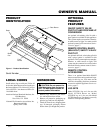
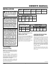
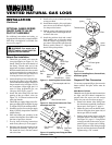
INSTALLING DAMPER
CLAMP
Secure the damper stop clamp provided to
the leading edge of the damper as shown in
Figure 5. If for any reason this clamp doesn't
work on your fireplace, another suitable
clamp or permanent stop must be installed,
or the damper blade must be cut or removed.
Damper Clamp
Damper
Clamp
Damper
Manufactured
Fireplace
Masonry Fireplace
Figure 5 - Attaching Damper Clamp
INSTALLATION
Continued
Damper
Damper
WARNING: Test all gas pip-
ing and connections for leaks
after installing or servicing. Cor-
rect all leaks at once.
WARNING: Never use an open
flame to check for a leak. Apply a
mixture of liquid soap and water
to all joints. Bubbles forming show
a leak. Correct all leaks at once.
CHECKING GAS
CONNECTIONS
Pressure Testing Gas Supply
Piping System
Test Pressures In Excess Of 1/2 PSIG
(3.5 kPa)
1. Disconnect log set and its individual
equipment shutoff valve from gas sup-
ply piping system.
2. Cap off open end of gas pipe where
equipment shutoff valve was con-
nected.
3. Pressurize supply piping system by either
using compressed air or opening main gas
valve located on or near gas meter.
4. Check all joints of gas supply piping
system. Apply mixture of liquid soap
and water to gas joints. Bubbles form-
ing show a leak.
5. Correct all leaks at once.
6. Reconnect log set and equipment
shutoff valve to gas supply. Check re-
connected fittings for leaks.
CONNECTING TO GAS
SUPPLY
WARNING: A qualified ser-
vice person must connect log set
to gas supply. Follow all local
codes.
Installation Items Needed
Before installing log set, make sure you
have the items listed below.
• piping (check local codes)
• sealant (resistant to propane/LP gas)
• equipment shutoff valve
• test gauge connection
• adjustable (crescent) wrench or pliers
• sediment trap
• tee joint
• pipe wrench
CAUTION: Use only new,
black iron or steel pipe. Inter-
nally-tinned copper tubing may
be used in certain areas. Check
your local codes. Use pipe of 1/2"
diameter or greater to allow
proper gas volume to log set. If
pipe is too small, undue loss of
pressure will occur.
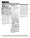
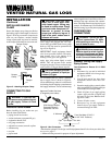
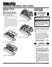
We recommend that you install a sediment
trap in supply line as shown in Figure 6.
Locate sediment trap where it is within reach
for cleaning. Install in piping system between
fuel supply and heater. Locate sediment trap
Installation must include a equipment shutoff
valve, union, and plugged 1/8" NPT tap.
Locate NPT tap within reach for test gauge
hook up. NPT tap must be upstream from
log set (see Figure 6).
IMPORTANT:
Install equipment shutoff
valve in an accessible location. The equip-
ment shutoff valve is for turning on or
shutting off the gas to the appliance.
Apply pipe joint sealant lightly to male
threads. This will prevent excess sealant
from going into pipe. Excess sealant in pipe
could result in a clogged burner injector.
CAUTION: Use pipe joint seal-
ant that is resistant to liquid pe-
troleum (LP) gas.
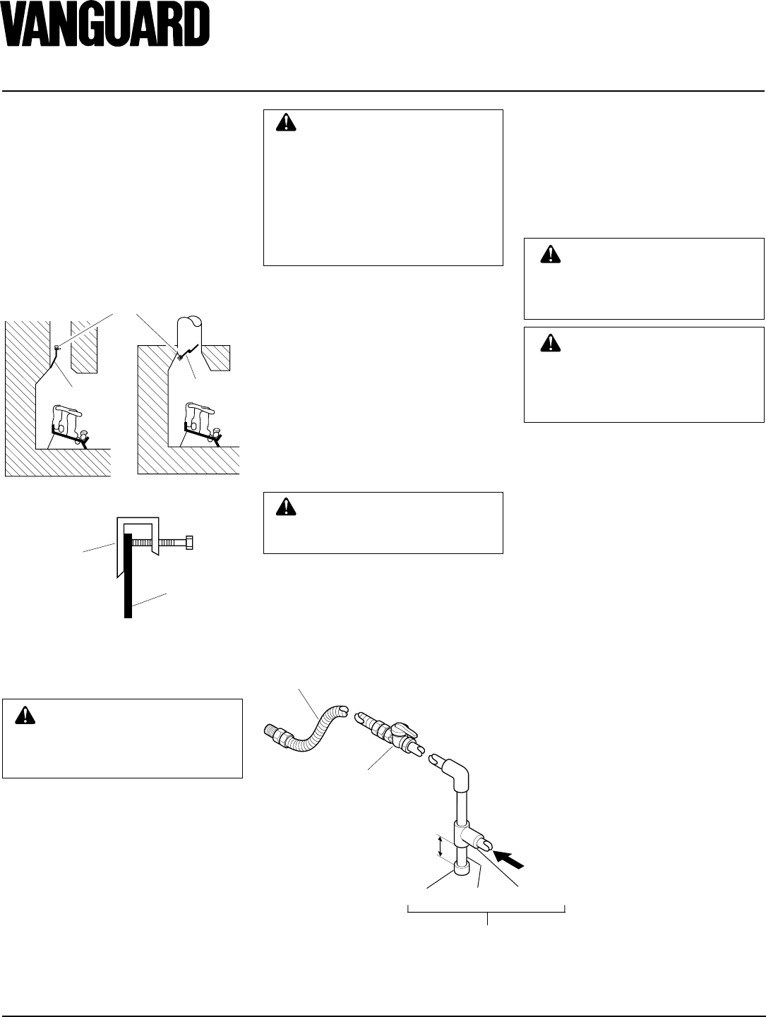
Figure 6 - Gas Connection
* Purchase the optional CSA design-certified equipment shutoff valve from your dealer. See
Accessories, page 17.
** Minimum inlet pressure for purpose of input adjustment.
3" Minimum
Sediment Trap
From Gas Meter (5" W.C.**
to 10.5" W.C. Pressure)
CSA Design-Certified
Equipment Shutoff
Valve With 1/8" NPT
Tap*
Approved Flexible Gas Hose
(if allowed by local codes)
Tee Joint
Pipe Nipple
Cap
where trapped matter is not likely to freeze. A
sediment trap traps moisture and contami-
nants. This keeps them from going into log set
controls. If sediment trap is not installed or is
installed wrong, log set may not run properly.