


Special offers from our partners!

Find Replacement BBQ Parts for 20,308 Models. Repair your BBQ today.

www.desatech.com
116236-01G 21
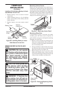
7. Check to make sure that the power cord is
completely clear of the blower wheel and that
there are no other foreign objects in blower
wheel. Also double check all wire leads and
make sure wire routing is not pinched or in a
precarious position. Correct accordingly.
8.
Turn on power to duplex outlet if previ-
ously turned off per the warning in column
1, page 19.
9. Plug in blower power cord to duplex outlet.
10. The blower will only run when the speed
control knob is in the ON position and the
thermal switch senses temperature after the
replace begins to heat up. The blower speed
can be adjusted by rotating the control knob.
To turn off, turn knob fully counterclockwise
until it clicks off. If the blower is ON and has
been running with the replace operating, the
blower will continue to run for a short time
after the replace has been turned off. As the
thermal switch cools down, the blower shuts
down automatically.
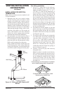
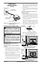
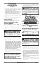
11. Peel off the backing paper and stick the sup-
plied wiring diagram decal on the rebox bot-
tom approximately 12" in front of the blower
(see Figure 28, page 20).
-
FIREPLACE
INSTALLATION
Continued
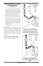
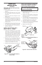
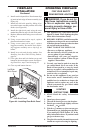
Figure 30 - Blower Wiring Diagram for
Thermostat-Controlled Models
Blue
Variable
Fan Switch
Fan Switch
(N.O.)
Green
White
On
110/115
V.A.C.
Blower
Motor
Black
Off
1
2
Black
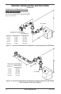
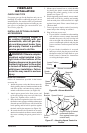
INSTALLING GAS PIPING TO
FIREPLACE LOCATION
WARNING: For natural
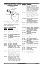
Installation Items Needed
Before installing replace, make sure you have
the items listed below.
• external regulator (supplied by installer)
• piping (check local codes)
• sealant (resistant to propane/LP gas)
• equipment shutoff valve *
• test gauge connection *
• sediment trap
• tee joint
• pipe wrench
• approved exible gas line with gas connector
(if allowed by local codes)
* A CSA design-certified equipment shutoff
valve with 1/8" NPT tap is an acceptable alterna-
tive to test gauge connection. Purchase the CSA
design-certied equipment shutoff valve from
your retailer.
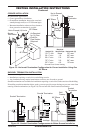
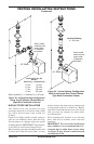
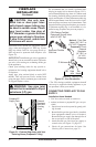
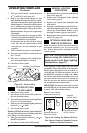
For propane/LP connection only, the installer
must supply an external regulator. The external
regulator will reduce incoming gas pressure. You
must reduce incoming gas pressure to between
11 and 14 inches of water. If you do not reduce
incoming gas pressure, replace regulator dam-
age could occur. Install external regulator with
the vent pointing down as shown in Figure 31,
page 22. Pointing the vent down protects it from
freezing rain or sleet.