


Special offers from our partners!

Find Replacement BBQ Parts for 20,308 Models. Repair your BBQ today.
www.desatech.com
111026-01C4
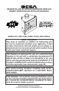
FIREPLACE INSTALLATION
SELECTING LOCATION
To determine the safest and most efcient location
for the replace, you must take into consideration
the following guidelines:
1. The location must allow for proper clearances
(see Figures 1 and 2).
2. Consider a location where the replace will
not be affected by drafts, air conditioning
ducts, windows or doors.
3. A location that avoids the cutting of joists or
roof rafters will make installation easier.
4. An outside air kit is available with this replace
(see Optional Outside Air Kit on page 8).
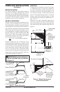
MINIMUM CLEARANCE TO
COMBUSTIBLES
Back and sides of replace 3/4" minimum*
Floor** 0" minimum
Perpendicular wall to opening 12" minimum
Top spacers 0" minimum
Mantel clearances
see Mantels, page 5
Chimney outer pipe surface 1" minimum
* Not required at nailing anges
** See step 2 of Framing
WARNING: Do not pack re-
quired air spaces with insulation
or other materials.
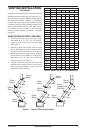
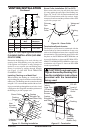
Minimum/Maximum Chimney Height for
Residential Installation
The minimum height of the chimney, measured
from the base of the replace to the ue gas outlet
of the termination, is 14.5 feet for straight ue or
a ue with one elbow set. The maximum distance
between elbows is 6 feet. For systems with two
elbow sets, the minimum height is 22 feet. The
maximum height of any system is 50 feet. This
measurement includes the replace, chimney sec-
tions and the height of the termination assembly
at the level of the ue gas outlet (see Figure 18,
page 11).
Minimum/Maximum Chimney Height for
Outdoor Installation
The minimum height of the chimney, measured
from the base of the replace to the ue gas outlet
of the termination, is 7
1
/
2
feet (minimum of 4 feet
of chimney pipe sections required for outdoor
installation).
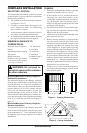
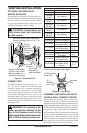
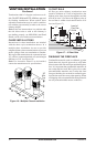
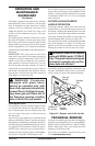
FRAMING
1. Frame the opening for the replace using the
dimensions shown in Figures 1 and 2.
2. If the replace is to be installed directly on
carpeting, tile (other than ceramic) or any
combustible material other than wood oor-
ing, the replace must be installed upon a
metal or wood panel extending the full width
and depth of the replace.
3. Set the replace directly in front of this open-
ing and slide the unit back until the nailing
anges touch the side framing.
4. Check the level of the replace and shim with
sheet metal if necessary.
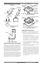
5. Before securing replace to prepared fram-
ing, the ember protector (provided) must
be placed between the hearth extension (not
supplied) and under the bottom front edge
of the replace to protect against glowing
embers falling through. If the replace is to be
installed on a raised platform, a Z-type ember
protector (not supplied) must be fabricated to
t your required platform height. The ember
protector should extend under the replace a
minimum of 1
1
/
2
". The ember protector should
be made of galvanized sheet metal (28 gauge
minimum) to prevent corrosion.
6. Using screws or nails, secure the replace to
the framing through anges located on the
sides of the replace.
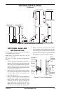
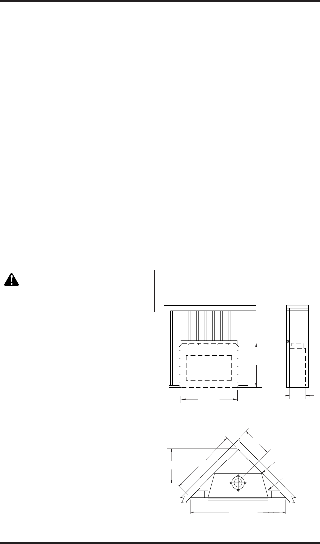
21.875”
41.375”
41.250”
Figure 1 - Framing Dimensions
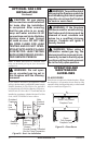
52.183"
17.253"
24.399"
73.798"
MAINTAIN
3
/
4
"
CLEARANCE AT
SIDES AND BACK
OF FIREPLACE
3
/4" CLEARANCE
NOT REQUIRED AT
NAILING FLANGES
Figure 2 - Corner Installation