


Special offers from our partners!

Find Replacement BBQ Parts for 20,308 Models. Repair your BBQ today.
7
55505
OUTSIDE OF
FIREPLACE
GAS LINE
CONDUIT
REMOVE
KNOCKOUT
SIDE FIREBRICK
FINISHED SIDE
REFRACTORY
KNOCKOUT PLUG
REMOVE BY TAPPING
LIGHTLY WITH A
1/2" DOWEL
AFTER REMOVING
GAS LINE COVER
PLATE, REPLACE
SCREWS
REMOVE
INSULATION
TEMPORARILY
(DO NOT
DISCARD)
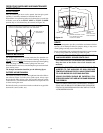
Figure 13
OUTSIDE OF
FIREPLACE
GAS LINE
CONDUIT
REPACK
INSULATION
INCOMING
1/2" BLACK
IRON PIPE
9
1
/
4
"
(235mm)
APPROX.
PROVIDE ENOUGH
THREADED END
FOR FITTING
CONNECTION
SEAL OPENING
WITH REFRACTORY
CEMENT
SIDE FIREBRICK
FINISHED SIDE
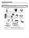
Figure 14
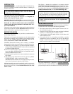
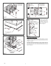
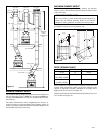
STEP 2: Remove gas line cover plate on rear of firebox and pull out
insulation from gas line conduit sleeve, save insulation for reuse.
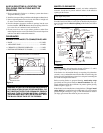
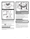
STEP 3: Run a 1/2" black iron gas line into the firebox through the
rear at 11
1
/4" from the floor and through gas line conduit sleeve (if
using a raised platform. Add height). Provide sufficient gas line into
firebox chamber for fitting connection (see Figure 14).
NOTE: Secure incoming line to wood framing to provide rigidity
for threaded end.
STEP 4: Repack insulation around gas line and into sleeve openings.
Seal any gaps between gas line and refractory knock out hole with
refractory cement or commercial furnace cement. Install the deco-
rative gas appliance or cap-off gas line if desired.
WARNING: All gas piping and connections must be
tested for leaks after the installation is completed.
After ensuring that the gas valve is on, apply a soap and water
solution to all connections and joints. If bubbles appear, leaks
can be detected and corrected.
DO NOT USE AN OPEN FLAME FOR LEAK TESTING
AND DO NOT OPERATE ANY APPLIANCE IF A LEAK
IS DETECTED.
The gas pipe is intended for connection to an unvented gas log set or
to a decorative gas appliance.
If you will install an unvented gas log set, ONLY UNVENTED GAS
LOG SETS WHICH HAVE BEEN FOUND TO COMPLY WITH THE
STANDARD FOR UNVENTED ROOM HEATERS, ANS/IAS/AGA
Z21.11.2, ARE TO BE INSTALLED IN THIS FIREPLACE.
NOTE: An appropriate Vanguard hood must be installed when
using an unvented gas log set.
WARNING: DO NOT OPERATE AN UNVENTED GAS
LOG SET IN THIS FIREPLACE WITH THE CHIMNEY
REMOVED.
If you will install a decorative gas appliance, the decorative gas
appliance must comply with the Standard for Decorative Gas
Appliances for Installation in solid Fuel burning Fireplaces,
ANS Z21.60-1996 and shall also be installed in accordance with the
National Fuel Gas code, ANS Z223.1-1996.
WARNING: WHEN USING A DECORATIVE APPLIANCE,
THE DAMPER MUST BE REMOVED OR PERMANENTLY
LOCKED IN THE FULLY OPEN POSITION.
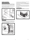
CHIMNEY PIPE INSTALLATION
The Vanguard chimney system is a snap-lock, double-wall pipe. It
consists of a stainless steel inner flue pipe, a galvanized outer pipe,
and a wire spacer.
Each section of pipe comes in lengths of 12", 18", 24", 36", and 48"
but the actual lineal gain for each is measured after each section is
fully connected.
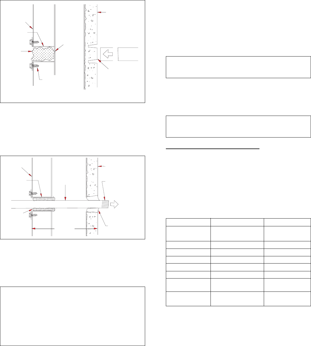
Lineal gain is the actual measurable length of a part after two or more
parts are connected.
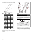
LINEAL GAIN
PART # NO. DESCRIPTION GAIN (inches)
VPN36 PENINSULA 66
1
/4"
FIREBOX
V12-10DM FLUE PIPE 10
3
/8"
V18-10DM FLUE PIPE 16
3
/8"
V24-10DM FLUE PIPE 23
3
/8"
V36-10DM FLUE PIPE 34
3
/8"
V48-10DM FLUE PIPE 46
3
/8"
VETL-10DM CHASE STYLE 7" to 17"
TERMINATION
VRTL-10DM ROUND TOP 6"
TERMINATION
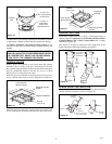
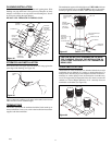
PIPE INSTALLATION
Place pipe assembly (inner and outer with wire spacer) over starting
collar. Inner pipe fits inside inner pipe, outer pipe fits outside
outer pipe.
Begin by aligning hemmed-end of inner flue pipe into the inner starting
flue pipe of firebox. Push down until hem "snap-locks" with lances. The
outer pipe is just the opposite; female end has the lances. Continue the
same procedure for the outer pipe (see Figure 15, page 8).