


Special offers from our partners!

Find Replacement BBQ Parts for 20,308 Models. Repair your BBQ today.
108796-01E
15
15
For more information, visit www.desatech.com
For more information, visit www.desatech.com
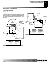
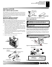
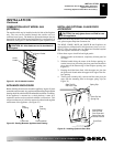
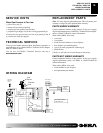
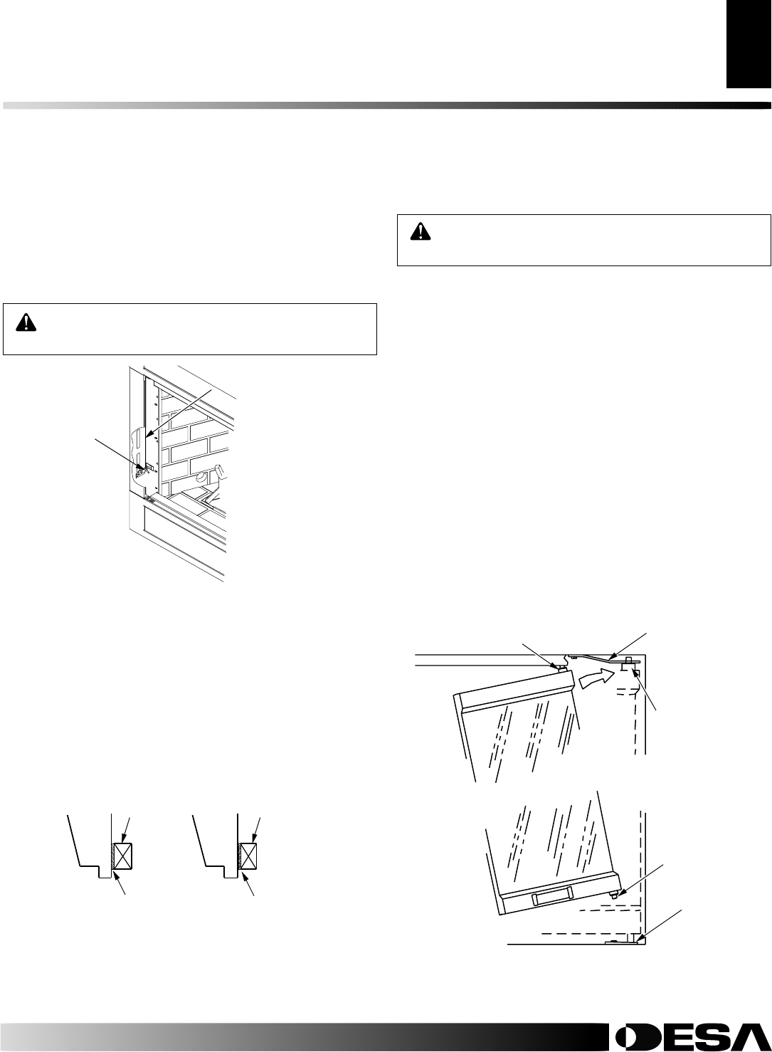
COMBUSTION AIR KIT MODEL AK4
(OPTIONAL)
The outside air kit may be installed on the left side of the fireplace
only. The vent can be installed through the outside wall or a
ventilated crawl space. The handle to operate the damper door for
the outside air inlet will be located inside the left “screen pocket” of
the firebox (see Figure 31). Pull the handle to open or push to close.
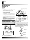
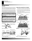
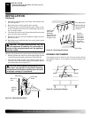
APPLIANCE ENCLOSURE
Before finishing the enclosure around the appliance, inspect all joints
around the outer surround. Any gaps between the nailing flanges and the
framing should be sealed with noncombustible insulation or caulking.
If the appliance is mounted on a raised platform, it must be a
continuous surface and not on blocks without a solid surface. This
will prevent the entry of cold air by means of conduction through the
total bottom of the appliance. (see Figure 32).
CAUTION: Air inlet ducts are not to terminate in
attic space.
Note:
Glass door may be heavy for some individuals. If this is the
case, please request help from someone else.
The M36E, VM36E, M42E and VM42E B-vent fireplaces are
approved for use with optional bi-fold glass doors (see Accessories,
page 27). The glass panels may be ordered and installed anytime
after the fireplace installation is complete.
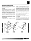
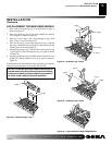
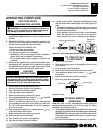
Follow these steps to install left and right panels:
1. With the handle at the bottom, completely fold the panel on
its hinges.
2. With the handle facing the center of the firebox opening, in-
sert the lower pivot pin on the glass door panel into the hole in
pivot plate on the bottom edge of the fireplace opening (see
Figure 33).
3. Keeping the folded door tilted, slide the upper two pins into
the guide track found under the upper facial edge of the fire-
box opening.
4. Tilt the glass assembly fully vertical until the outer pivot pin
snaps into the mounting hole in the upper spring clip (see
Figure 33).
INSTALLING OPTIONAL GLASS DOOR
ACCESSORY
CAUTION: Use only glass doors certified for use
with this appliance.
Figure 31 - Air Kit Handle Location
Air Kit
Handle
Side
Framing
Side
Framing
Caulk Here
Pack Insulation
Figure 32 - Sealing Between Appliance and Framing
INSTALLATION
Continued
Figure 33 - Installing Optional Glass Door
Spring Clip
Insert Pin Into
Spring Clip
Insert Bottom
Pivot Pin Into
Pivot Plate and
Swing Door Into
Vertical Position
Pivot Plate
Slide Top Pin
Into Door Track
Screen Pocket
INSTALLATION
Combustion Air Kit Model AK4 (Optional)
Appliance Enclosure
Installing Optional Glass Door Accessory