


Special offers from our partners!

Find Replacement BBQ Parts for 20,308 Models. Repair your BBQ today.
111922-01B
For more information, visit www.desatech.com
For more information, visit www.desatech.com
22
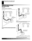
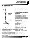
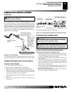
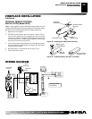
WALL SWITCH INSTALLATION
The installation of a wall switch allows you to activate the gas
control valve and turn the fireplace on and off. The wall switch is
to be connected to the incoming 120 volt regular household wiring
that supplies the electricity to the fireplace. Refer to wiring
diagram below.
FIREPLACE INSTALLATION
Continued
FIREPLACE INSTALLATION
Installing Logs, Lava Rock and Glowing Embers
Wall Switch Installation
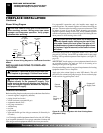
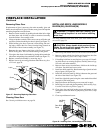
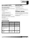
6. Rest log #8 (left crossover log) onto log #3 and rest log #9 (right
crossover log) onto logs #4 and #5 as shown in Figure 42.
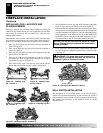
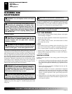
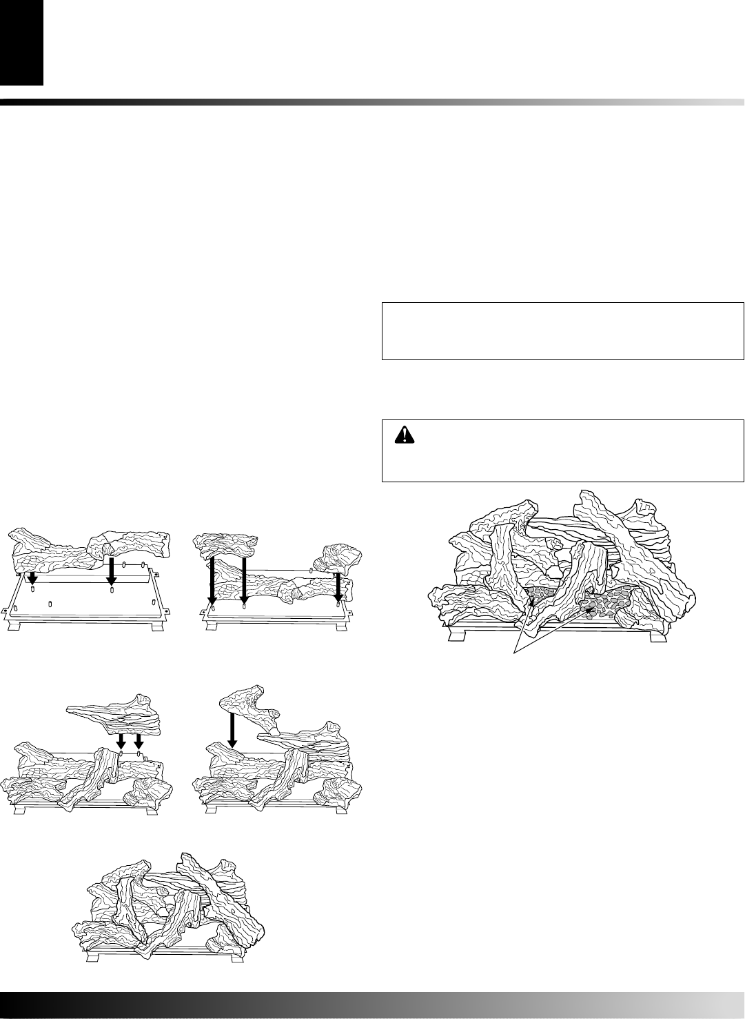
7. Pull ember material apart into pieces no larger than a dime. Place
these pieces loosely and sparingly directly onto the exposed front
section of the burner (see Figure 44). This will create the glowing
ember appearance as the flame touches the ember material. Do
not block air slots by using too much ember material in one area.
It is not necessary to use all of the ember material provided.
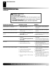
Figure 42 - Installing Log No. 7
Figure 41 - Installing Logs
No. 5 and No. 6
5
6
7
NOTICE: Do not put lava rock on burner or under
burner. Placing lava rock on burner will cause perfor-
mance problems.
Ember Material
Figure 44 - Placing Ember Material on Burner
8
9
Figure 43 - Installing Logs No. 8 and No. 9
WARNING: The glass door must be securely in
place before running this fireplace. Do not run this
fireplace if glass is missing or broken.
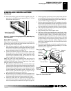
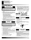
INSTALLING LOGS, LAVA ROCK AND
GLOWING EMBERS
Each log is marked with a number. These numbers will help you
identify the log when installing. It is very important to install these
logs exactly as instructed. Do not modify logs. Only use logs
supplied with fireplace.
Open louvers, remove screen, unlock door latches, and open glass
door. See Removing/Replacing Glass Door, steps 1 and 2 on page 21.
Install logs according to instructions for fireplace model numbers.
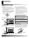
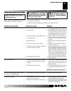
1. Place log #1 (left base log) onto pin on left side of burner as
shown in Figure 39.
2. Place log #2 (right base log) onto pin on right side of burner as
shown in Figure 39.
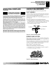
3. Place logs #3 (left front log) and log #4 (right front log) onto
pins as shown in Figure 40.
4. Place log #5 (right rear log) onto pins on right rear of burner
(see Figure 41). Rest log #6 (middle crossover log) on top of
log number 2 as shown in Figure 41.
5. Place back end of log #7 (left rear log) onto pin on left rear
burner and rest front onto log #1 as shown in Figure 42.
Figure 39 - Installing Logs
No. 1 and No. 2
Figure 40 - Installing Logs
No. 3 and No. 4
1
2
3
4
8. Close glass door, lock door latches, replace screen, and close
louvers (see Removing/Replacing Glass Door, steps 5 through
7 on page 21).