


Special offers from our partners!

Find Replacement BBQ Parts for 20,308 Models. Repair your BBQ today.
www.desatech.com
113133-01B 11
INSTALLATION
Continued
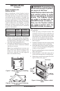
BUILT-IN FIREPLACE
INSTALLATION
Built-in installation of this fireplace involves
installing fireplace into a framed-in enclosure.
This makes the front of fireplace flush with wall.
An optional trim kit accessory is available (see
Accessories, page 40). Trim will extend past sides
of fireplace approximately 1/2 inch. This will cover
the rough edges of the wall opening. If installing
a built-in mantel above the fireplace, you must
follow the clearances shown in Figure 10, page
12. Follow the instructions below to install the
fireplace in this manner.
Actual Framing
Height 26" 26
7
/8"
Front Width 26
3
/4" 26
7
/8"
Depth 14
1
/4" 15
1
/4"
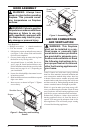
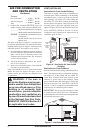
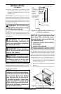
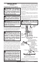
1. Frame in rough opening. Use dimensions shown
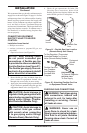
in Figure 7 for the rough opening. If installing in
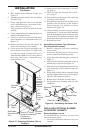
a corner, use dimensions shown in Figure 8 for
the rough opening. The height is 26
7
/8" which
is the same as the wall opening above.
2. If installing GA3450TA blower accessory, do
so at this time. Follow instructions included
with blower accessory.
Note: If not installing blower accessory, you
may wish to run electrical wiring to your
fireplace for future blower installation (see
Accessories, page 40). Use only approved
three-wire electrical wiring.
WARNING: If pre-wiring, do
not connect wiring to any electri-
cal source at this time.
Install fireplace electrical outlet
and connect wiring to outlet
before connecting to electrical
source. The fireplace electri-
cal outlet is included with the
GA3450TA blower accessory.
Only use the fireplace electri
-
cal outlet supplied with the
GA3450TA blower accessory.
Note: A qualified installer should make all electri-
cal connections.
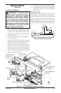
3. Install gas piping to fireplace location. This
installation includes an approved flexible gas
line (if allowed by local codes) after the equip
-
ment shutoff valve. The flexible gas line must
be the last item installed on the gas piping.
4. If you have not installed hood, follow instruc
-
tions on page 6.
5. Carefully set fireplace in front of rough opening
with back of fireplace inside wall opening.
6. Attach flexible gas line to fireplace gas regula
-
tor. See Connecting Equipment Shutoff Valve
to Heater Control,
page 17.
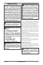
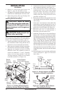
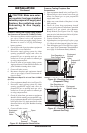
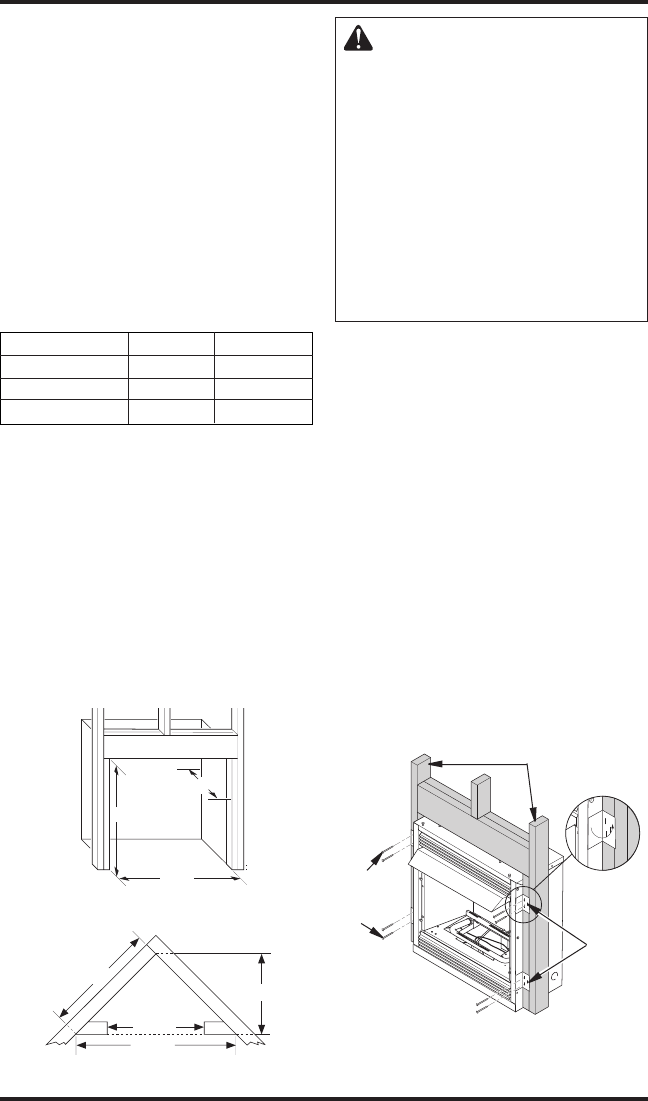
7. Bend four nailing flanges on outer casing with
pliers (see Figure 9).
8. Attach fireplace to wall studs using nails or
wood screws through holes in nailing flange.
9. Check all gas connections for leaks. See Check
-
ing Gas Connections, page 17.
Figure 8 - Rough Opening for Installing
in Corner
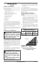
Figure 7 - Rough Opening for Installing
in Wall
43
5
/
16
"
30
5
/
8
"
61
1
/
4
"
26
7
/
8
"
26
7
/8"
26
7
/8
"
3/4" Off
The Floo
r
Minimum
15
1
/4
"
Figure 9 - Attaching Fireplace to Wall
Studs
Nailing
Flanges
Nails or
Wood
Screws
Wall Studs