


Special offers from our partners!

Find Replacement BBQ Parts for 20,308 Models. Repair your BBQ today.
108796-01E
11
11
For more information, visit www.desatech.com
For more information, visit www.desatech.com
INSTALLATION
INSTALLATION
Wall Switch Installation
Optional Remote Control Installation
Gas Line Hook-Up
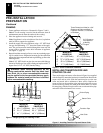
OPTIONAL REMOTE CONTROL
INSTALLATION (Model WRC)
Note:
If using optional wireless hand-held remote control, the wall
switch must be in the ON position to be operational. The remote control
then becomes the switching mechanism for fireplace operation.
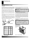
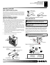
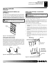
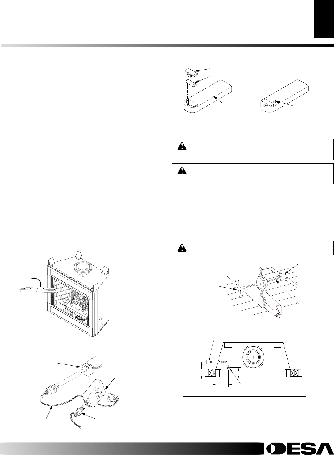
1. Remove the front refractory access panel by lifting up and an-
gling out of the firebox opening (see Figure 13).
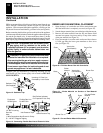
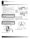
2. The WRC model receiver does not require a battery. The re-
ceiver can be installed by first plugging the short extension
cord into the fireplace receptacle. Then plug the receiver unit
into the extension cord. Finally plug the ignition module plug
into the receiver unit (see Figure 14).
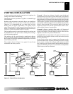
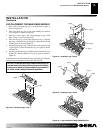
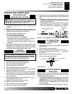
3. Activate the remote handset battery by removing the insulat-
ing tab on the back of the handset (see Figure 15). The battery
is included pre-installed.
4. Once the battery is activated the unit is ready to use.
5. Replace front refractory access panel.
WALL SWITCH INSTALLATION
The installation of a wall switch allows you to activate the gas
control valve and turn the fireplace on and off. The wall switch is to
be connected to the incoming 120 volt regular household wiring that
supplies the electricity to the fireplace. Refer to wiring diagram in
this manual on page 19.
Figure 14 - Installing the WRC Remote Receiver
Fireplace
Receptacle
Remote Control
Receiver
Extension Cord
Ignition
Module Plug
Figure 15 - Installing Battery into Back of Handset
Pull to Remove
Insulation Tab
Battery Cover
12 Volt Battery
Back of
Handset
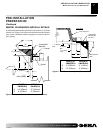
GAS LINE HOOK-UP
WARNING: Gas line hookup should be done by
your gas supplier or a qualified service person.
WARNING: Before you proceed, make sure your
gas supply is OFF.
CAUTION: Do not kink flexible gas line.
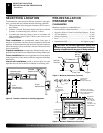
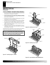
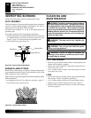
A manual shutoff valve has been included in the appliance’s gas supply
system. You may consider installing an extra gas shutoff valve outside the
appliance’s enclosure (check with local codes) where it can be accessed
more conveniently with a key through a wall as shown in Figure 16.
In conformance with local codes, route a 1/2" NPT gas line to the
appliance through hole in left side of firebox or sub-floor as shown
in Figure 17.
Figure 16 - Manual Shutoff Valve Installation
Figure 17 - Routing Incoming Gas Line
Typical Exterior Wall Gas
Shutoff Installation
Key
Extension
Shutoff
Valve
A
1/2" NPT Incoming
Black Iron Gas Line
7"
7"
Alternate Gas Supply
Through Sub-Floor
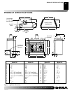
M36E(B,H) M42E(B,H)
VM36E(B,H) VM42E(B,H)
A8
5
/8" (219mm) 10
1
/2" (267mm)
Figure 13 - Removing Front Refractory Access Panel