


Special offers from our partners!

Find Replacement BBQ Parts for 20,308 Models. Repair your BBQ today.

8
107063
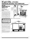
UNVENTED NATURAL GAS FIREPLACE
LFP33NRA
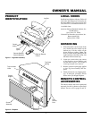
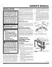
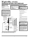
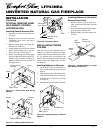
Figure 8 - Placing Hearth Base Accessory
Against Wall
Figure 9 - Installing Cabinet Mantel
Electrical
Outlet
Hearth
Base
Flexible
Gas Line
Gas Line
Access
Hole
Cabinet
Mantel
INSTALLATION
CLEARANCES
WARNING: Maintain the mini-
mum clearances. If you can, pro-
vide greater clearances from
floor, ceiling, and adjoining wall.
CONVENTIONAL FIREPLACE
INSTALLATION
Conventional installation of this fireplace
involves installing fireplace along with the
corner, face, or cabinet mantel with hearth
base accessories against a wall in your home.
Follow the instructions below to install the
fireplace in this manner.
Note:
The instructions below show installa-
tion using the cabinet mantel and hearth
base accessories (see Accessories, pages 24
and 25). The hearth base accessory shown is
optional for this installation. You can install
fireplace and cabinet mantel directly on the
floor. The corner mantel accessory cannot
be installed with the hearth bases. You must
install corner mantel directly on the floor.
1. Assemble cabinet mantel, hearth base,
and trim accessories. Assembly instruc-
tions are included with each accessory.
2. When installing blower, install a prop-
erly grounded, 120 volt three-prong
electrical outlet at fireplace location if
an outlet is not there. If possible, lo-
cate outlet so cabinet mantel will cover
it when installed (see Figure 8).
3. Install gas piping to fireplace location.
This installation includes an approved
flexible gas line (if allowed by local
codes) after the equipment shutoff
valve. The flexible gas line must be the
last item installed on the gas piping. See
Installing Gas Piping to Fireplace Lo-
cation, page 10.
4. Place hearth base accessory against
wall at installation location. Cut an ac-
cess hole in hearth top to run flexible
gas line to fireplace (see Figure 8).
Make sure to locate access hole so cabi-
net mantel will cover it when installed.
Note:
You can secure base to floor us-
ing wood screws. Countersink screw
heads and putty over.
5. Route flexible gas line through access
hole in hearth base.
6. Center cabinet mantel on hearth base
(see Figure 9). Make sure mantel is
flush against wall.
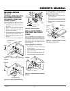
7. Break off nailing flanges (see Figure 10,
page 9) with hammer or pliers.
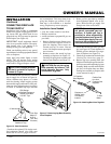
INSTALLATION
Continued
8. Place cardboard or other protective
material on top of hearth base. Care-
fully set fireplace on protective mate-
rial, with back of fireplace inside man-
tel opening.
9. Attach flexible gas line to fireplace gas
regulator. See Connecting Fireplace to
Gas Supply, page 11.
10. If blower is installed, route blower elec-
trical cord through access holes in ei-
ther side of fireplace.
Note:
Bushing
may be moved if necessary. Plug elec-
trical cord into electrical outlet.
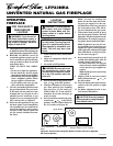
Carefully follow the instructions below. This
will ensure safe installation.
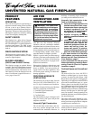
Minimum Clearances For Side
Combustible Material, Side Wall,
and Ceiling
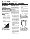
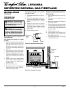
A. Clearances from the side of the fire-
place cabinet to any combustible ma-
terial and wall should follow diagram
in Figure 7.
Example:
The face of a mantel, book-
shelf, etc. is made of combustible ma-
terial and protrudes 3
1
/2" from the wall.
This combustible material must be 4"
from the side of the fireplace cabinet
(see Figure 7).
B. Clearances from the top of the fireplace
opening to the ceiling should not be less
than 42 inches.
Figure 7 - Minimum Clearance for
Combustible to Wall
.5 2
7/16
7/8
1
3
/
4
3
1
/
2
5
1
/
4
7
8
3
/
4
10
1
/
2
12
1
/
4
1 4 6 8 10 12 14 16
FIREBOX
INCHES
INCHES
*Minimum 16 inches from Side Wall
*
Example