


Special offers from our partners!

Find Replacement BBQ Parts for 20,308 Models. Repair your BBQ today.
www.desatech.com
55173-F8
FIREPLACE
INSTALLATION
Continued
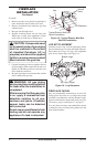
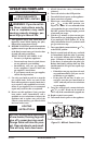
OPTIONAL OUTSIDE AIR KIT
(MODEL AK-4)
The installation of an outside air kit should be
completed during the rough framing of the fire-
place due to the nature of it's location. Outside
combustion air is accessed through a vented
crawl space.
CAUTION: Air inlet ducts
must not be terminated in an
attic space.
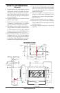
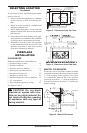
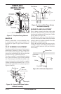
Avoid installing outside air eyebrow in areas where
inlet opening may be blocked by snow, bushes or
other obstacles (see Figure 10).
The maximum height for the air inlet termination
cannot exceed 3 feet below the B-vent termination
exhaust height.
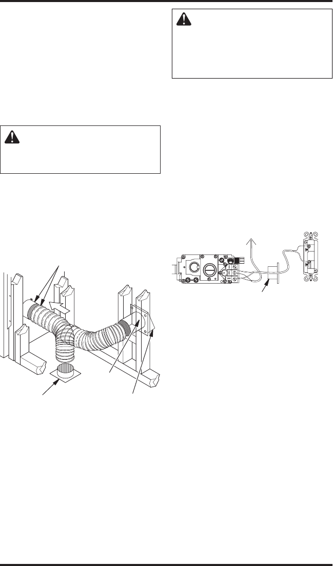
Figure 10 - Outside Air Kit
Secure to Collars with Duct Tape or
Screws
Air Inlet
Location
Must Allow
For Bushes
or Snow
Vent Hood
Required for
Wall Installation
Air Inlet
Eyebrow
Vented Crawl Space
(Check Local Codes
Before Installing in a
Vented Crawl Space)
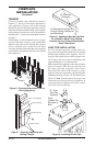
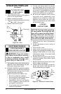
MILLIVOLT MODELS (GL36ST/STP)
The installation of a wall switch in this millivolt
control appliance allows you to activate the gas
control valve without the use of normal current.
CAUTION: Do not connect
this millivolt system wall switch
to a regular 120v power source!
Gas valve will be damaged be-
yond repair.
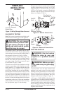
Wall Switch Installation
1. Remove the J-box cover plate from side of
applianceʼs outer surround.
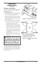
2. Using the 18 ga. millivolt wire and wall switch
(both supplied), connect wiring per wiring
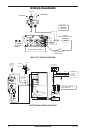
diagram (see Figure 11). For more detail, see
Wiring Diagrams
on page 16.
Note: If any of the original 10 feet supplied wire
must be replaced, use Thermostat Millivolt Wire
18 AWG Type CL2-105 C or equivalent only.
IMPORTANT: Do not hook up to standard 120
VAC household wiring.
Figure 11 - Wall Switch Installation
O
F
P
I
L
O
T
O
N
F
T
O
I
P
L
7
TP
T
H
TP
TH
Wall Switch
(Supplied)
Back View
To Thermopile
Route Millivolt Wires
(Supplied) Through
Electrical Conduit Bushing
ELECTRONIC MODELS (GL36STE/EP)
This appliance must be properly wired to standard
120v household current through the DESA-pro
-
vided wall switch before its remote control unit
can be used to activate the automatic pilot ignition
(turn fireplace flames ON).
Wall Switch Installation
1. Remove the J-box cover plate from side of
applianceʼs outer surround.
2. Using the 18 ga. wires coming through strain
relief grommet on side of applianceʼs outer
wall to standard household 120 VAC current
through the wall switch provided, as shown in
Figure 12, page 9. For more detail, see Wiring
Diagrams, page 16.
Note: If any of the original 10 feet supplied wire
must be replaced, use 20 AWG electrical wire or
equivalent only.