


Special offers from our partners!

Find Replacement BBQ Parts for 20,308 Models. Repair your BBQ today.
www.desatech.com 112462-01C
22
INSTALLATION
Continued
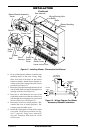
OPTIONAL WALL MOUNTED
THERMOSTAT - GWMT1
(Remote-Ready Models Only)
WARNING: Read and follow
installation instructions. Instal-
lation should be done by a quali-
fied installer familiar with low-
voltage wiring procedures.
WARNING: Do not connect
this thermostat to any electrical
source! Electrical shock and/or
fire hazard will occur.
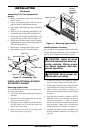
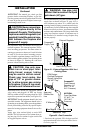
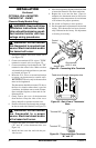
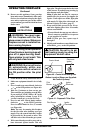
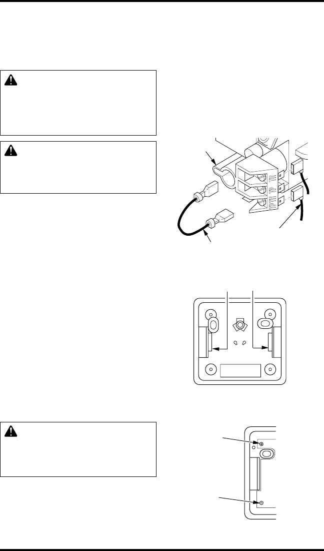
1. Disconnect jumper wire from control valve
(see Figure 32).
2. Connect one terminal of 25 ft. wire to "TPTH"
terminal on control valve (see Figure 32).
3. Connect remaining wire terminal to the “TH”
terminal on the control valve. Make sure that
wire terminals are in the positions on your unit
as pictured in Figure 32.
4. Route the 25 ft. wire to a convenient location
to mount your thermostat (no outside wall).
IMPORTANT:
The wire may be shortened but
must not be lengthened.
The thermostat should be mounted 54" above
the floor in a location where there is good air
circulation. Avoid heat sources such as lamps,
direct sunlight, fireplace, or heat and air con-
ditioning ducts.
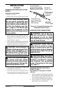
5. Gently remove the cover of the thermostat
from the base. Grasp the sides of the cover
firmly and pull to separate from the base.
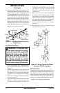
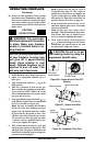
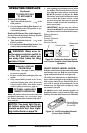
6. Feed the electrical wires through the rectangu-
lar slots on each side of the base (see Figure 33).
WARNING: Do not connect
the thermostat to a power
source. Electrical shock and/or
a fire hazard will occur.
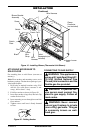
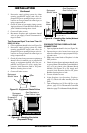
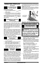
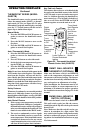
6. Connect one bare wire end to each terminal
(“W” and “R”) of the thermostat base (see
Figure 34).
7. Install the base onto the wall with the pro-
vided screws.
Figure 32 - Connecting Wire Terminals
One terminal
of 25 ft. wire
Control
Valve
Jumper Wire
8. Move the temperature adjustment back and forth
to insure the bimetal is free from restrictions.
9. Replace the cover onto the base. (Upon in-
stallation, the thermostat must be allowed to
stabilize at room temperature for a minimum
of 30 minutes for proper operation).
10. Set switch on fireplace to Auto position.
11. Set the temperature adjustment to the desired
setting. This thermostat has been electroni-
cally calibrated at the factory. No adjustment
or leveling is necessary.
Figure 33 - Back View of Thermostat
Base
Feed wires through rectangular slots
W
R
Figure 34 - Thermostat Base Terminals
“W” and “R”
Terminal “W”
Terminal “R”