


Special offers from our partners!

Find Replacement BBQ Parts for 20,308 Models. Repair your BBQ today.
17
106424
OWNER’S MANUAL
FIREPLACE
INSTALLATION
Continued
WARNING: Never touch the
blower wheel while in operation.
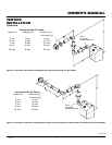
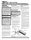
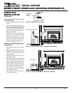
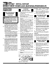
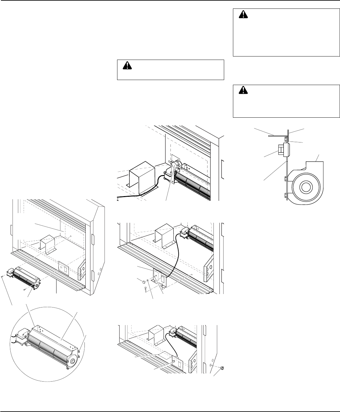
10. Peel off the backing paper and stick the
supplied wiring diagram decal on the
firebox bottom approximately 3" to the
right of the blower speed control
bracket (Figure 32).
WARNING: Failure to position
the parts in accordance with sup-
plied diagrams or failure to use
only parts specifically approved
with this heater may result in dam-
age or personal injury.
11. Connect or reconnect gas supply to fire-
place per Connecting Fireplace to Gas
Supply on page 19 of this manual.
8. Plug in blower power cord.
a. If your fireplace system is installed
as a freestanding unit with an ac-
cessory mantel, determine whether
the power cord will exit the left side
or the right side of the firebox. In-
stall one plastic bushing provided
into the 1
1
/2" hole in the outer cas-
ing through which the power cord
will exit. Install the second plastic
bushing provided into the floor sup-
port bracket if exiting through the
right side (see Figure 32). Route
power cord through (both) plastic
bushing(s) and plug the power cord
into a properly grounded 3-prong
wall receptacle near the firebox.
b.If your fireplace system installation
is recessed and/or pre-wired, a
qualified installer must make all elec-
trical connections for the outlet kit
included with the fireplace.
WARNING: A qualified ser-
vice person must connect fire-
place to gas supply. Follow all
local codes.
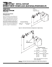
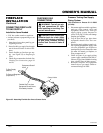
Figure 31 - Attaching Speed Control to
Firebox
Figure 32 - Installing Plastic Bushing and
Wiring Diagram Sticker
Continued
9. Check to make sure that the power cord
is completely clear of the blower wheel
and that there are no other foreign ob-
jects in blower wheel. Turn blower on
and check for operation. Turn blower
off by rotating knob fully counterclock-
wise before continuing.
Plastic Bushing
Wiring
Diagram
Blower Speed
Control Bracket
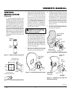
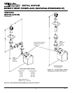
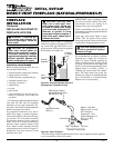
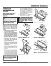
Figure 30 - Locating Thermal Switch Against Back of Firebox
Thermal Switch
Side View
Firebox Bottom
Firebox Back
Firebox Flange
Blower
Thermal
Switch
Thermal
Switch
Bracket
Control
Knob
Locknut
Control Shaft
Speed
Control
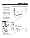
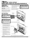
Figure 29 - Mounting Blower to Firebox
Top
Mounting
Tab
Exhaust Port
Blower
Screws
Lower Louver
Panel
Lower Rear
Wall of
Firebox
Wrapper