


Special offers from our partners!

Find Replacement BBQ Parts for 20,308 Models. Repair your BBQ today.

10
901049
VENTED NATURAL GAS LOGS
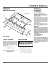
OPTIONAL GA9050 SERIES
ON/OFF SAFETY VALVE/
PILOT KIT ASSEMBLY
For additional convenience and safety, or
for propane/LP conversion, an optional ON/
OFF safety valve/pilot kit is available. See
Accessories, page 17.
WARNING: You must use a
ON/OFF safety valve/pilot kit for
propane/LP conversion.
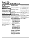
Natural Gas Installation
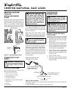
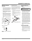
1. Thread the gas control valve onto the
close pipe nipple (see Figure 11). Use
thread sealant on the male threads of
the fitting. Thread other end of the
nipple into the burner manifold block.
Hold the manifold block with a wrench
to prevent stressing the connections to
the burners. Make sure the control rod
is facing the front (see Figure 11).
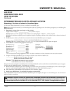
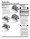
2. Attach the pilot gas line to the pilot out-
let of the gas control valve and tighten.
Connect the thermocouple to the rear of
the gas control valve (see Figure 12). Do
not overtighten. If using propane/LP gas,
see Changing Pilot Orifice, page 11.
3. Install the inlet fitting into the inlet
opening of the gas control valve (see
Figure 13). Use thread sealant on the
male pipe threads.
4. Thread the gas supply fitting to the fire-
place gas supply pipe (see Figure 10,
page 9). Adjust to most convenient po-
sition.
5.
Install the gas flex line to the gas supply
fitting. Carefully shape tube to attach to
adapter fitting.
6. Place the burner pan assembly in the
center of the fireplace floor. Make sure
the front of pan faces forward.
7. Test for leaks following instructions
under Testing Burner for Leaks, page 11.
8.
Retighten and adjust the location of the
gas control as necessary. The gas con-
trol should be level, with the control
Close Pipe
Nipple
Gas
Control
Valve
Manifold
Block
Figure 11 - Installing Gas Control Valve
Control Rod
INSTALLATION
Continued
rod to the front.
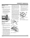
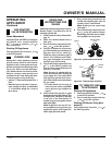
9. Install valve cover to burner pan using
screws provided.
10. Install thermocouple, pilot, and ignitor
onto valve cover as shown in Figure 14.
Use the provided screws.
11. Push the control rod extension onto the
“D” shaped control rod through the cen-
ter hole in the cover.
12.
Install the position decal and control
knob making sure to align the marks
with the correct stop positions of the
gas control. Pilot position will allow the
knob to push in about 1/2". Align the
decals in the pilot position.
Figure 12 - Gas Control Valve with Ther-
mocouple and Pilot
Figure 13 - Installing Inlet Fitting and Gas
Connector Tube
Piezo Ignitor
Control
Rod
Extension
Screw
Valve
Cover
Control Knob
Figure 14 - Installing Cover, Control Knob,
and Piezo Ignitor
Thermocouple and Line
Pilot and Line
Gas Control Valve
Gas Control
Valve
Gas Inlet
Fitting
Flex Gas
Line
Thermocouple
Ignitor
Pilot
Inlet
Opening
Burner
Pan
Propane/LP Gas Conversion
To convert to propane/LP gas, the burner
inlet fitting must be removed and pilot ori-
fice must be replaced.
Burner Inlet Fitting
Note:
Be sure all pipe threaded connections
are tight, and have thread compound to
prevent leaks. Be sure to use the correct
orifice for your unit. See chart on page 7.
1. Remove the burner inlet fitting from
the front burner manifold (installed in
burner pan). See Figure 15, page 11.
2. Make sure ports on front burner mani-
fold are facing the front (open side) of
burner pan. Refit if needed.
3. Replace front burner injector with the
provided injector. See chart on page 7
and Figure 16, page 11. Using thread
sealant (resistant to the action of pro-
pane/LP gas) on larger end of fitting,
screw the burner inlet fitting through
the hole and into the burner manifold.
Tighten using a 7/8" wrench.