


Special offers from our partners!

Find Replacement BBQ Parts for 20,308 Models. Repair your BBQ today.
111906-01E
For more information, visit www.desatech.com
For more information, visit www.desatech.com
16
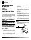
FIREPLACE INSTALLATION
CHECK GAS TYPE
Use proper gas type for the fireplace unit you are installing. If your
gas supply is not correct, do not install fireplace. See retailer where
you purchased the fireplace for proper fireplace according to your
gas type or to purchase gas conversion kit (see Accessories, page 38).
INSTALLING OPTIONAL BLOWER
ACCESSORIES
NOTICE:The CHDV42NR-B model fireplace comes
with the BKT Blower already installed as standard
equipment. If you have a CHDV42NR-B model fire-
place, proceed to
Installing Gas Piping to Fireplace
Locations
, page 19.
NOTICE: If installing blower in an existing fireplace
with gas connections, shut off gas supply and dis-
connect heater from gas supply. Contact a qualified
service person to do this.
WARNING: If there is a duplex electrical outlet
installed in the right side of the bottom of the fireplace
base area, be sure that the electrical power to the outlet
is turned off before proceeding with blower installation.
Failure to do this may result in serious injury.
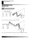
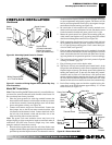
Model BK Installation
Follow all instructions provided in the blower accessory kit.
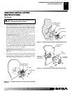
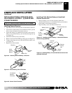
1. Attach the power cord to the blower motor by firmly pushing the
two female terminals at the end of the power cord onto the two
spade terminals on the blower motor (see Figure 25).
2. Attach green ground wire from power cord to blower housing
using screw provided (see Figure 25). Tighten screws securely.
3. Place the blower against the lower rear wall of the firebox outer
wrapper with the exhaust port directed upward. The blower
will fit inside the back opening and be held in position against
the back wall by the magnets (see Figure 25).
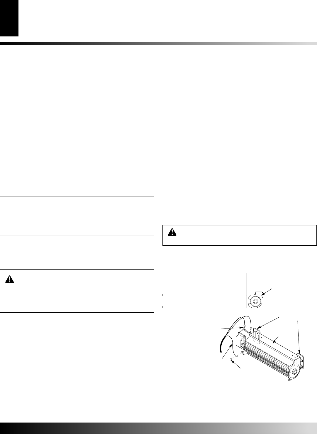
Figure 25 - Blower Model BK
Magnetic Strips
Exhaust
Port
Screw
Green
Ground Wire
Spade Terminals
Side View
Lower Firebox
Cavity
Blower
Location
4. Be certain that all wire terminals are securely attached to ter-
minals on blower motor and that the screw retaining the green
ground wire is tight.
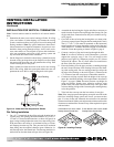
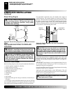
5. Mount speed control box to switch bracket by placing the plastic
control shaft forward through the round opening in the switch
bracket (see Figure 26, page 17).
6. While supporting speed control, secure control shaft with lock
nut by pushing and turning lock nut with pliers clockwise until it
is tight against front panel. Place control knob provided on shaft.
7. Turn on power to duplex outlet if previously turned off per the
warning in column 1.
8. Plug in blower power cord.
a. If your firebox is installed as a freestanding unit with an
accessory mantel, determine whether the power cord will
exit the left side or the right side of the firebox. Route power
cord through exit hole and plug the power cord into a wall
receptacle near the firebox.
b. If your firebox installation is recessed and/or pre-wired,
plug the power cord into the duplex outlet provided. Refer
to your firebox owner’s manual for instructions on wiring
the duplex outlet.
9. Check to make sure that the power cord is completely clear of the
blower wheel and that there are no other foreign objects in blower
wheel. Turn blower on and check for operation. Turn blower off
by turning knob fully counterclockwise before continuing.
CAUTION: Never touch the blower wheel while in
operation.
VENTING INSTALLATION
INSTRUCTIONS
Continued
VENTING INSTALLATION INSTRUCTIONS
Parts Lists for Venting Kits and Components
FIREPLACE INSTALLATION
Check Gas Type
Installing Optional Blower Accessories
PARTS LISTS FOR VENTING KITS AND COMPO-
NENTS (CONT.)
Number Description
FP-58 Firestop Plate
SF-58 Stucco Flashing - For use with HTS-5
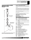
10. Peel off the backing paper and stick the supplied wiring dia-
gram decal on the firebox bottom approximately 12" in front
of the blower (see Figure 27, page 18).