


Special offers from our partners!

Find Replacement BBQ Parts for 20,308 Models. Repair your BBQ today.
108796-01E
12
For more information, visit www.desatech.com
For more information, visit www.desatech.com
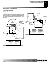
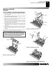
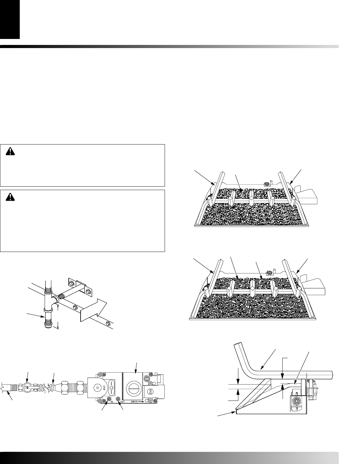
EMBER AND PAN MATERIAL PLACEMENT
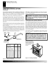
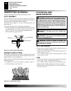
1. Open the bag(s) of vermiculite and fill the entire burner pan
until the burner tube is completely covered (see Figure 20).
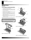
2. Smooth the pan material just even with edges of the burner pan.
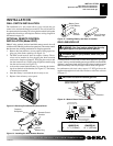
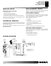
3. Remove the ember material from the bag and flatten small
amounts into quarter size pieces and lay on top of the surface
of the pan material (see Figure 21).
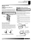
4. Place just enough to cover the entire surface and leave about a
1/2 inch gap under the lower grate members to allow air to
flow (see Figure 22).
INSTALLATION
Continued
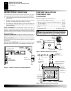
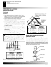
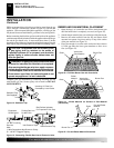
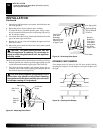
DESA recommends that a black iron gas line be routed from the gas
source, through a sediment trap (shown in Figure 18), and into the
appliance, Once connected through the appliance, a flexible gas line
may be used for ease of installation to gas control valve (see Figure19).
Before connecting the black iron gas line to the inside of the appliance
a sediment trap must be included outside the appliance between the gas
line and the gas shutoff valve. It must extend down three (3) inches
beyond the center of the pipe. Prepare incoming black iron gas line with
teflon tape or pipe joint compound (Check with local building codes).
WARNING: All gas piping and connections must
be tested for leaks after the installation is completed.
After ensuring that the gas valve is on, apply a commer-
cial leak detection solution to all connections and joints.
If bubbles appear, leaks can be detected and corrected.
Do not use an open flame for leak testing and do not
operate any appliance if a leak is detected.
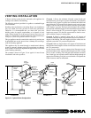
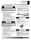
Complete your gas installation by connecting incoming gas line
with flexible gas line. Secure tightly with wrench but DO NOT
OVERTIGHTEN.
CAUTION: Compounds used on threaded joints
of gas piping shall be resistant to the action of
Liquefied Petroleum (LP or propane), and should be
applied lightly to ensure excess sealant does not
enter the gas line.
3" Min.
(76mm)
Side Wall
Of Appliance
Incoming 1/2" Gas Line
Permitted by Local Codes
Sediment Trap
(Not Supplied)
Figure 18 - Sediment Trap
Figure 20 - Fill Entire Burner Pan with Vermiculite
Figure 21 - Ember Material on Surface of Pan Material
(Vermiculite)
0.5"
0.5"
Figure 22 - Pan and Ember Material Clearances
Vermiculite
(Pan Material)
Burner Pan
Grate
Ember
Material
Burner Pan
Vermiculite
(Pan Material)
Grate
Grate
Burner Pan
Pan and Ember
Material
INSTALLATION
Gas Line Hook-Up (Cont.)
Ember and Pan Material Placement
Figure 19 - Connecting Flexible Gas Line to Electronic Valve
1/2" NPT Incoming
Gas Line
Inlet Pressure Tap
Outlet Pressure Tap
Equipment
Shutoff Valve
Flexible Gas Line
Do NOT Kink
Note:
1) Wire Connections Not Shown for Clarity
2) * 1/8" NPT Plugged Tapping
Red Surface Indicates
For Propane/LP Use Only