


Special offers from our partners!

Find Replacement BBQ Parts for 20,308 Models. Repair your BBQ today.
21
106517
OWNER’S MANUAL
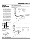
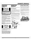
To Wall
Thermostat
FIREPLACE
INSTALLATION
Continued
Continued
INSTALLING OPTIONAL
WALL MOUNTED
THERMOSTAT - GWMT1
WARNING: Installation must
be done by a qualified installer
familiar with low voltage wiring
procedures.
WARNING: Do not connect
this thermostat to any electrical
source! Electrical shock and/or
fire hazard will occur.
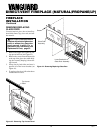
1. Open lower louver panel. The valve is
attached to the underside of the firebox
assembly.
2. Disconnect from the valve the wires
running from the ON/OFF switch.
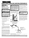
3. Connect one terminal of the provided
wire for the wall thermostat to the
TPTH terminal on the valve. Connect
remaining wire terminal to the TH ter-
minal on the valve. Make sure that the
wire terminals are in the positions on
the unit as pictured in Figure 40. If
wires are not connected as shown the
thermostat will not work.
4. Route the wire through openings pro-
vided on the sides of the fireplace to a
convenient location to mount your ther-
mostat (no outside wall).
IMPORTANT:
The wire may be short-
ened but must not be lengthened.
The thermostat should be mounted 54"
above the floor in a location where
there is good air circulation. Avoid
heat sources such as lamps, direct sun-
light, fireplace, or heat and air condi-
tioning ducts.
WARNING: Do not connect
this thermostat to a power
source. Electrical shock and/or
fire hazard will occur.
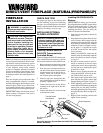
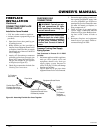
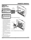
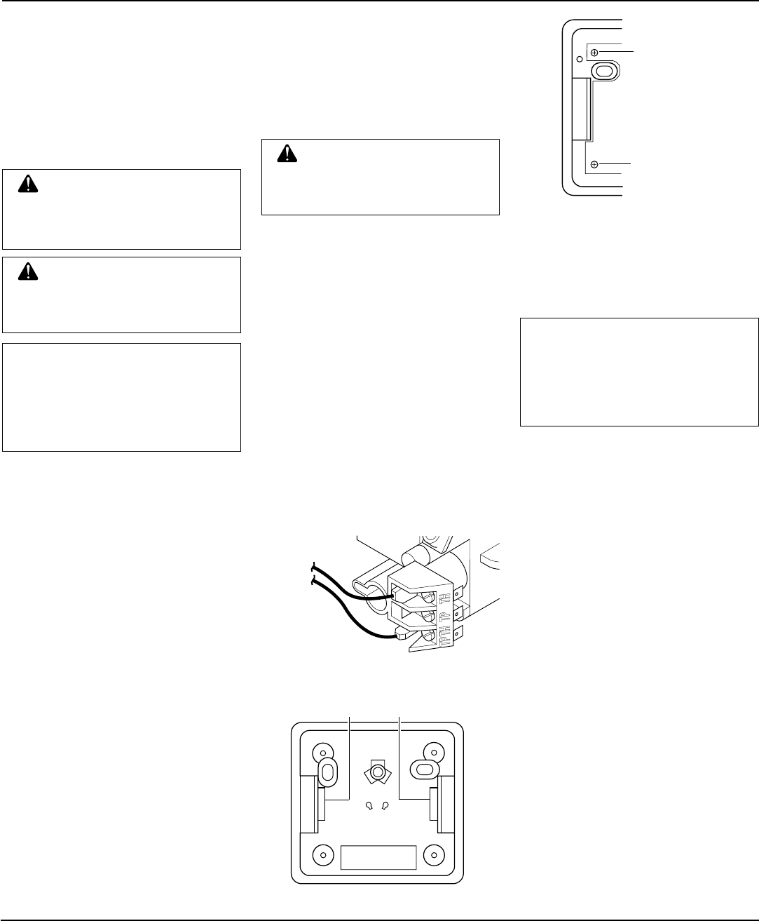
Feed wires through
rectangular slots
Figure 41 - Back View of Thermostat Base
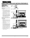
Figure 42 - Thermostat Base Terminals
“W” and “R”
Figure 40 - Control Valve Terminals
5. Gently remove the cover of the ther-
mostat from the base. Grasp the sides
of the cover firmly and pull to separate
from the base.
6. Feed the electrical wires through the
rectangular slots (from the back) on
each side of the base (see Figure 41).
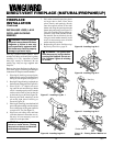
INSTALLING OPTIONAL
WALL MOUNT SWITCH
GWMS2
W
R
Terminal “W”
Terminal “R”
NOTICE: The GWMT1 includes 25'
of wire for installation. Your fire-
place includes 15' of wire for ac-
cessory installation. Choose the
length that best fits your needs
when installing this accessory.
7. Connect one bare wire end to each ter-
minal (“W” and “R”) of the thermostat
base (see Figure 42).
8. Install the base to the wall with screws
provided with thermostat.
9. Move the temperature adjustment back
and forth to insure the bi-metal is free
from restrictions.
10. Replace the cover onto the base. (Upon
installation, the thermostat must be al-
lowed to stabilize at room temperature
for a minimum of 30 minutes for proper
operation.)
11. Set the temperature adjustment to the
desired setting.
This thermostat has been electronically
calibrated at the factory. No adjustment
or leveling is necessary.
NOTICE: The GWMS2 includes
25' of wire for installation. Your
fireplace includes 15' of wire for
accessory installation. Choose the
length that best fits your needs
when installing this accessory.
1. Connect one terminal of the provided
wire for the wall switch to the TPTH
terminal on the valve. Connect remain-
ing wire terminal to the TH terminal on
the valve. Make sure that the wire ter-
minals are in the positions on the unit as
pictured in Figure 40. If wires are not
connected as shown the switch will not
work.
2. Route the wire through openings pro-
vided on the sides of the burner sys-
tem to a convenient location to mount
your switch.
3. Connect one bare wire end to each of
the terminals of the GWMS2 wall
switch.
4. Install the wall switch and cover in the
wall.