Special offers from our partners!

Find Replacement BBQ Parts for 20,308 Models. Repair your BBQ today.
6
WARNING
This installation must conform to local codes or, in
the absence of local codes, with either the National
Fuel Gas Code, ANSI Z223.1/NFPA 54, Natural
Gas and Propane Installation Code, CSA B149.1, or
Propane Storage and Handling Code, B149.2.
Prevent grill combustion products from being drawn
into a building through fresh air inlets: The venting
system of other than a direct-vent appliance must
terminate at least 4 feet (1.2m) below, 4 feet (1.2m)
horizontally from, or 1 foot (305mm) above any door,
window or gravity air inlet into any building. The
bottom of the vent terminal must be located at least
12 inches (305mm) above grade.
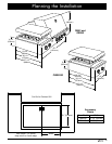
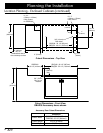
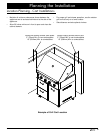
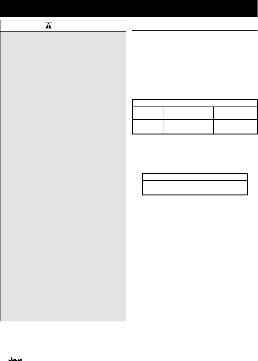
A MINIMUM clearance of 10 inches (254mm) must
be maintained, above the countertop material, from
all combustible vertical materials on the sides and
behind the outdoor grill chassis and canopy.
On all models except OBSB162, a MINIMUM
clearance of 1 1/4 inches (32mm) must be
maintained, above the countertop material, from all
non-combustible vertical materials on the sides and
behind the outdoor grill chassis and canopy.
On model OBSB162, a MINIMUM clearance of
2 inches (51mm) must be maintained, above the
countertop material, from all non-combustible vertical
materials on the sides and behind the chassis.
A MINIMUM clearance of 1/4 inch (6mm) must be
maintained, inside the base enclosure below the
countertop material, from all vertical surfaces on the
sides of the appliance, except on model OBSB162.
On model OBSB162 a minimum clearance of 1/4
inch (6mm) must be maintained in back and 1/16
inch on the sides.
A MINIMUM clearance of 3/4 inch (19mm) must be
maintained, from the bottom of the control panel to
any material for ventilation purposes. Failure to do
so will block air flow through the outdoor grill and
may cause carbon monoxide poisoning or improper
operation.
The back edge of the grill must maintain a minimum
clearance (10 inches/254mm) from combustible back
splash materials. Special cabinet and countertop
dimensions are required.
The electrical outlet and gas service must be
installed only by a qualified, licensed professionals.
The maximum gas supply pressure to the regulator
must not exceed 1/2 pound per square inch.
•
•
•
•
•
•
•
•
•
•
Planning the Installation
Gas and Electric Power Requirements
Prior to installation, the gas supply for natural gas
or whole house LP installations must meet the
specifications below.
For natural gas or whole house LP installations, have a
qualified plumber or gas fitter install a 3/4 inch (19mm)
or 1/2 inch (13mm) gas supply line with a shut off
valve (not included). Have it installed in an accessible
location that allows it to be shut off when the appliance
is installed.
Correct voltage, frequency and amperage must be
supplied to the appliance from an isolated, grounded
circuit which is protected by a properly sized circuit
breaker or time-delay fuse. The required voltage,
frequency, and amperage ratings are listed on the
product data plate and are also below.
It is the owner’s responsibility to ensure that the
electrical connection to this appliance is installed by a
qualified electrician. The electrical installation, including
minimum supply wire size and grounding, must be
done in accordance with National Electric Code ANSI/
NPFA 70, (or the latest revision) or Canadian Electrical
Code CSA C22.1, and local codes and ordinances for
connection of an outdoor appliance.
Locate the electrical outlet within reach of the 48 Inch
(1219mm) long power cord so that it will reach when
the grill is completely installed in the enclosure.
Total connected loads shown include the ignition
system, interior lights and rotisserie motor.
The rotisserie motor should be plugged into the same
grounded outlet power source or an alternate 120 Vac
duplex outlet located on the same circuit as the grill.
•
•
•
•
•
•
•
Location Planning - General
Electrical Requirements
Circuit Requirement 120 Vac, 15 A
Total Connected Load 2.9 Amps, (0.35 Kw)
Gas Supply Requirements
Model Type Manifold Pressure
Minimum Gas
Supply Pressure
Natural Gas 4” Water Column 5” Water Column
LP Gas 11” Water Column 12” Water Column


