


Special offers from our partners!

Find Replacement BBQ Parts for 20,308 Models. Repair your BBQ today.
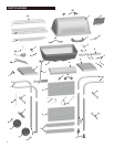
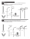
Burner
Assembly
Heat Shield
Ignitor
wire
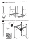
8
(A)
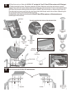
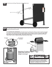
(C)Insidefirebox,attachfireboxandcontrolpanelwith5mmID,16mmODfiberwashersand#8sheetmetalscrews
.
(D)Attachignitorwiretoelectrode.
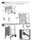
Shelf
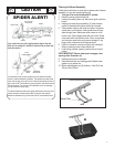
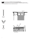
Correctly assembled valve in burner tube and venturi clips
B
B
Venturi clip
Venturi tube
Heat shield
Firebox
Control knobs
A
#10-24x1-1/4"
Carriage Bolt
Qty . 4
#8 Sheet Metal
Screw
Qty . 2
9
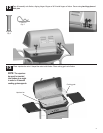
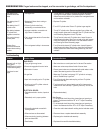
Attach side shelves with #10-24x1-3/4" machine screws.
D
Ignitor wire
C
V a l v e
Left side
Right side
#10-24
Wing Nut
Qty . 4
5mm
Fiber washer
Qty . 2
#10-24x1-3/4"
Machine Screw
Qty . 8
21
7mm
Fiber W asher
Qty . 4
#8 Sheet
Metal Screw
5mm
Fiber washer
Venturi clip
Qty. 2
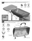
Place firebox onto cart. Attach with #10-24x1-1/4" carriage bolt, 7mm ID, 16mm OD fiber washersand#10-24wingnut.
(B) Position heat shield as shown. Place burner assembly into firebox. Make sure venturi tubes and valves are correctly
engaged. Place small end of venturi clipinto venturi tube and large part of clip around valve. If burner is not leveled from left to
right, adjust the two screws attaching valveto control panel in step 8B. Place control knobs on valves as shown in figure (A).
Place heat shield onto burner venturi tube, then insert burner/ heat shield through venturi holes on firebox. Make sure ignitor
wire go through the hole on heat shield and firebox as shown.