


Special offers from our partners!

Find Replacement BBQ Parts for 20,308 Models. Repair your BBQ today.
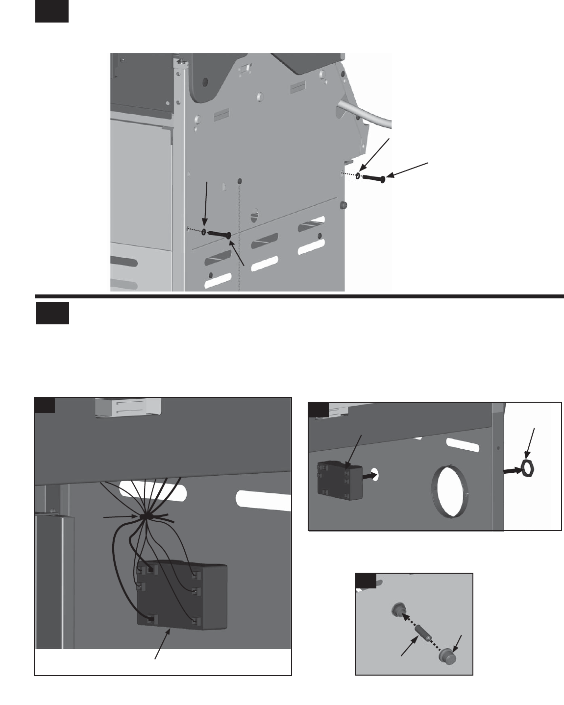
12
21
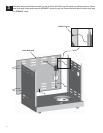
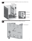
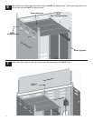
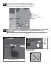
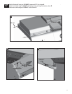
Secure front brace in upper hole with one 1/4-20x1½” screw and fiber washer.
Secure upper back panel in lower hole with one 1/4-20x1½” screw and fiber washer.
Only left side shown for assembly, repeat above steps for right side.
Upper back
panel
1/4-20x1½” screw
Fiber washer
Fiber washer
1/4-20x1½” screw
13
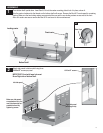
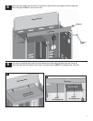
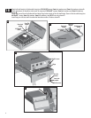
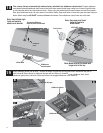
Inside of the cart, connect the wires from burner electrodes into the back of Electronic Ignition module. Total (5) connections.
Note: Switch terminals are larger than electrode terminals and should only be installed in location shown as (a),(b).
Connect the two wires [(a) and (b)] from switch wiring harness into the back of Electronic Ignition module. Total (2)
connections, shown A.
1
(a)
(b)
2
3
4
5
Electronic ignition module
+
-
Cap
AA battery
Right side panel
C
A
B
Nut
Electronic ignition
Tie wrap
Right side panel
module
NOTE: Wires omitted for
clarity of illustration
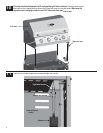
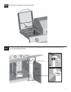
Release the cap and nut from electronic ignition module. Attach electronic ignition module to the cart right side panel
with the nut, shown B.
Insert AA battery into ignition module, negative (
–) end first. Then put on the cap, shown C.