


Special offers from our partners!

Find Replacement BBQ Parts for 20,308 Models. Repair your BBQ today.
11
Majestic Fireplaces® BR/BC Series
7412944
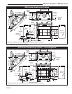
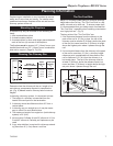
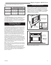
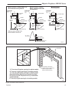
The following table gives firestop spacer model num-
bers:
The inside dimension of the frame must be the same
as the hole size selected from Figure 13 in order to
provide the required 1¹⁄₂" (38 mm) of air space between
the outside diameter of the chimney and the edges of
the framed ceiling hole.
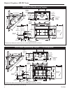
Positioning, Safety Strips,
Securing the Fireplace
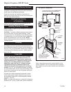
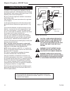
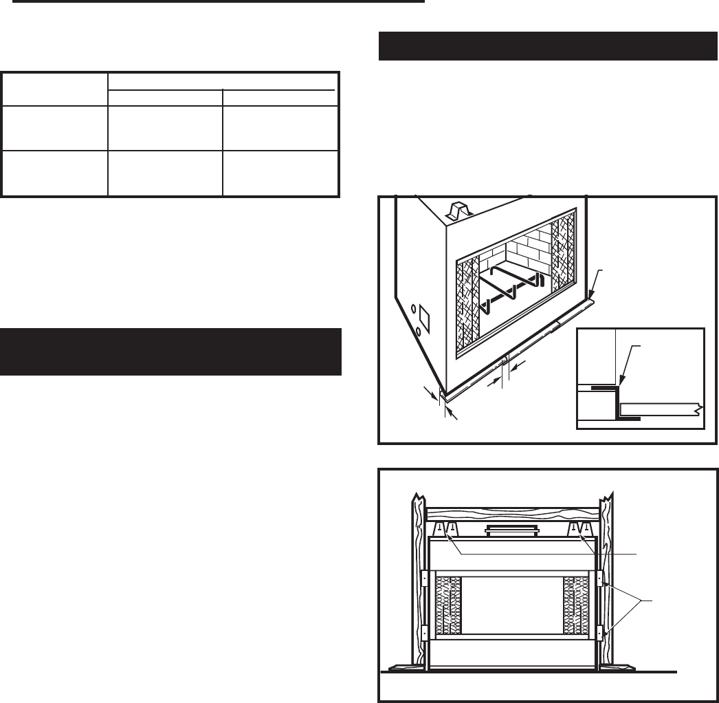
Slide fireplace into position.
Lift the fireplace front slightly and slide the metal safety
strips under front bottom edge about 1¹⁄₂" (38 mm), al-
lowing the remainder to extend in front of firebox. Over-
lap strips at least 1/2" (13 mm) to provide a positive
joint. (Flat safety strips are packed with fireplace.) (Fig. 14)
Safety strips are used to ensure that any combustible
materials in front of the fireplace are protected even
though a noncombustible hearth extension is required.
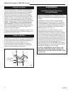
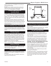
If fireplace is to be elevated above the floor, a “Z”
shaped metal safety strip must be fabricated and used
to protect combustible surfaces in front of the fireplace.
This “Z” shaped safety strip is not provided but must be
fabricated of metal with each horizontal leg at least 1¹⁄₂"
(38mm) wide and equal in length to the metals strips
provided with the fireplace.
Note: Safety strips are not required over noncombusti-
ble floors where all supports at the base of the fireplace
are noncombustible.
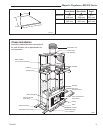
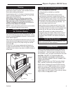
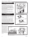
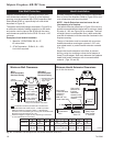
Four (4) nailing flanges are supplied with the fireplace
(found on the fireplace hearth). To level the box and
secure it firmly in place, remove the nailing flanges from
the hearth and install at the sides of the fireplace as
shown in Figure 15.
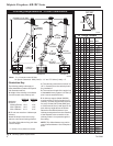
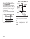
Installing Outside Air Kit
An outside air kit is installed in all BR/BC Series Fire-
places. If desired, or if local codes mandate the use of
an air kit, then an AK-MST is required to complete the
installation (from air kit to the outdoors). If the outside
air kit is to be used, the AK-MST MUST be installed BE-
FORE the fireplace is enclosed. Refer to the AK-MST
instructions for field installation.
FP549
Fig. 15 Fasten fireplace in position.
FP549
9/29/97
BR/BC
Nail Top
Standoffs
Nail Side-
Nailing
Flanges
Fig. 13 Ceiling chimney hole sizes necessary for installing
firestop spacer.
Size of Chimney Vertical 30°
8" Flue SKFS2A SKFS6A
"SK" Series 14¹⁄₂" x 14¹⁄₂" 14¹⁄₂" x 25¹⁄₂"
(368 mm x 368 mm) (368 mm x 648 mm)
8" Flue FS2A FS6A
"S" Series 3-Wall 17¹⁄₂" x 17¹⁄₂" 17⁷⁄₈" x 29⁵⁄₈"
(445 mm x 445 mm) (454 mm x 753 mm)
Angle of Chimney at Ceiling
WF557
BR
11/10/97
¹⁄₂" (13mm)
Min. Overlap
1¹⁄₂
"
(38mm)
"Z"
Safety
Strip
Fire-
Place
Plat-
Form
Hearth Ext.
(not supplied)
FP557
Fig. 14 Safety strip installation.
Metal Safety Strip
(1,2 or 3 pieces)