


Special offers from our partners!

Find Replacement BBQ Parts for 20,308 Models. Repair your BBQ today.
Page 16 B101361-0-1008
GAS CONVERSION TO NATURAL GAS
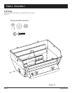
1. Remove cooking grids, flavor screen or, briquets and
briquet rack from grill.
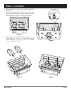
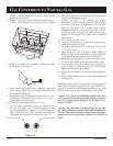
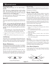
2. Remove burners and burner shields from grill (one (1)
1/4-20 x 3/4 phillips screw for each burner). See Figure
17.
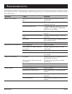
3. Remove LP burner orifice marked 1.25mm from each
orifice fitting. See Figure 18.
4. Install natural gas burner orifice marked 49 into each
orifice fitting. Apply pipe compound to threads on ori-
fices prior to installation.
5. Place burners into grill and insert burner tubes over ori-
fice fittings. Secure each burner with one (1) 1/4-20 x
3/4 phillips screw from Step 2.
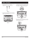
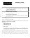
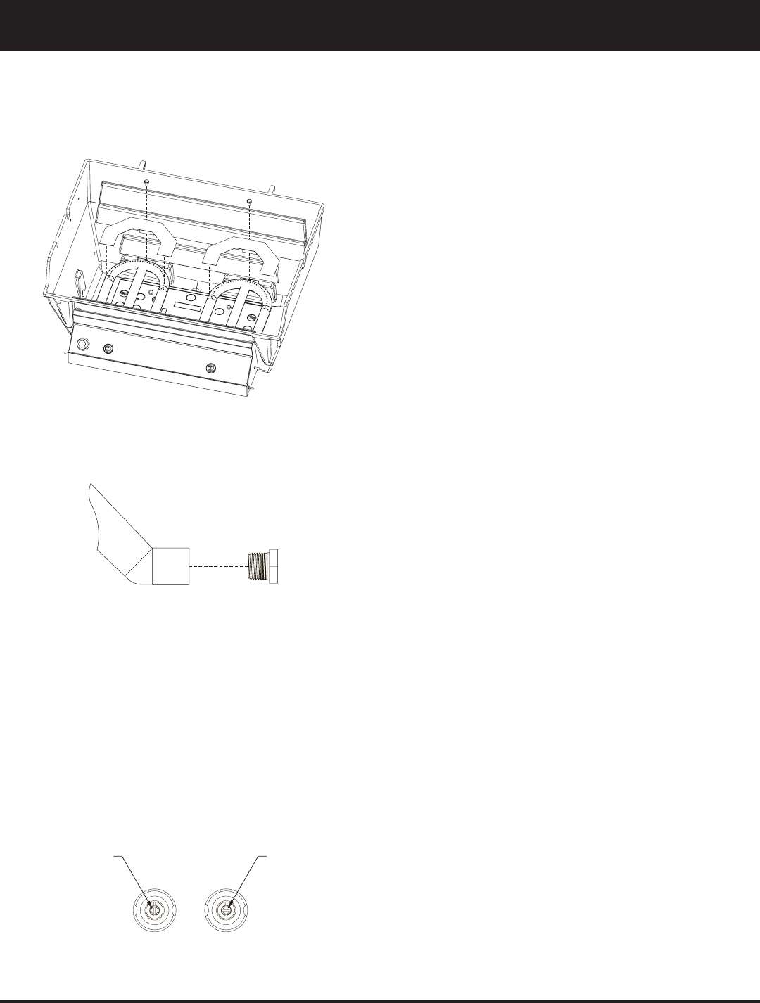
6. Grasp valve knobs and remove from valves.
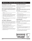
7. The low input adjustment screws are located inside
the two valve stems. Use a small screwdriver to turn
each adjustment screw clockwise 1/4 turn (90 degrees).
When valves are in the "OFF" position, the slot in the
adjustment screw should be vertical. See Figure 19.
8. Remove the hose and regulator from the gas connection
on grill with adjustable wrench.
9. Connect the grill to the natural gas supply.
Attention: Before lighting your grill check all gas
connections including the adjustment screws in valve
stems for gas leaks with a soapy water mixture.
Caution: Do not use the grill if a gas leak is detect-
ed until gas leak is corrected. If a gas leak can not be
stopped, do not use grill. You must contact a qualified
repair person.
10. Push valve knobs onto valves.
11. Apply the completed conversion label adjacent to the
rating plate label on the grill.
12. The natural gas inlet pressure at the grill is to be set at
7.0" of inlet pressure.
13. Ignite burners on grill and observe flame pattern. If
flame is yellow in color or flame is lifting off burner,
the air shutter on burners will require adjustment.
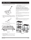
14. Beneath the control panel you can access the air shut-
ters which are located on the end of the burner tubes.
15. Loosen phillips screw at air shutter, open air shutter for
a yellow flame or close air shutter for a lifting flame.
Tighten phillips screw at air shutter.
16. Ignite burners on grill to verify burner flame character-
istics.
17. Replace flavor screen or briquet rack and briquets and
cooking grids.
Installation must conform to local codes or in the absence of
local codes, with the National Fuel Gas Code, ANSI Z223.1/
NFPA 54, Natural Gas and Propane Installation Code, CSA
B149.1, or Propane Storage and Handling Code, B149.2.
Caution: The grill and its individual shutoff valve must
be disconnected from the gas supply piping system dur
-
ing any system pressure testing at test pressures in ex-
cess of 1/2 PSIG.
Caution: The grill must be isolated from the gas sup
-
ply piping system by closing its individual manual shut-
off valve during any pressure testing of the gas supply
piping system at test pressures equal to or less than 1/2
PSIG.
Figure 17
Figure 18
LPG
NA
T
ADJUSTMENT SCREW
ADJUSTMENT SCREW
Figure 19